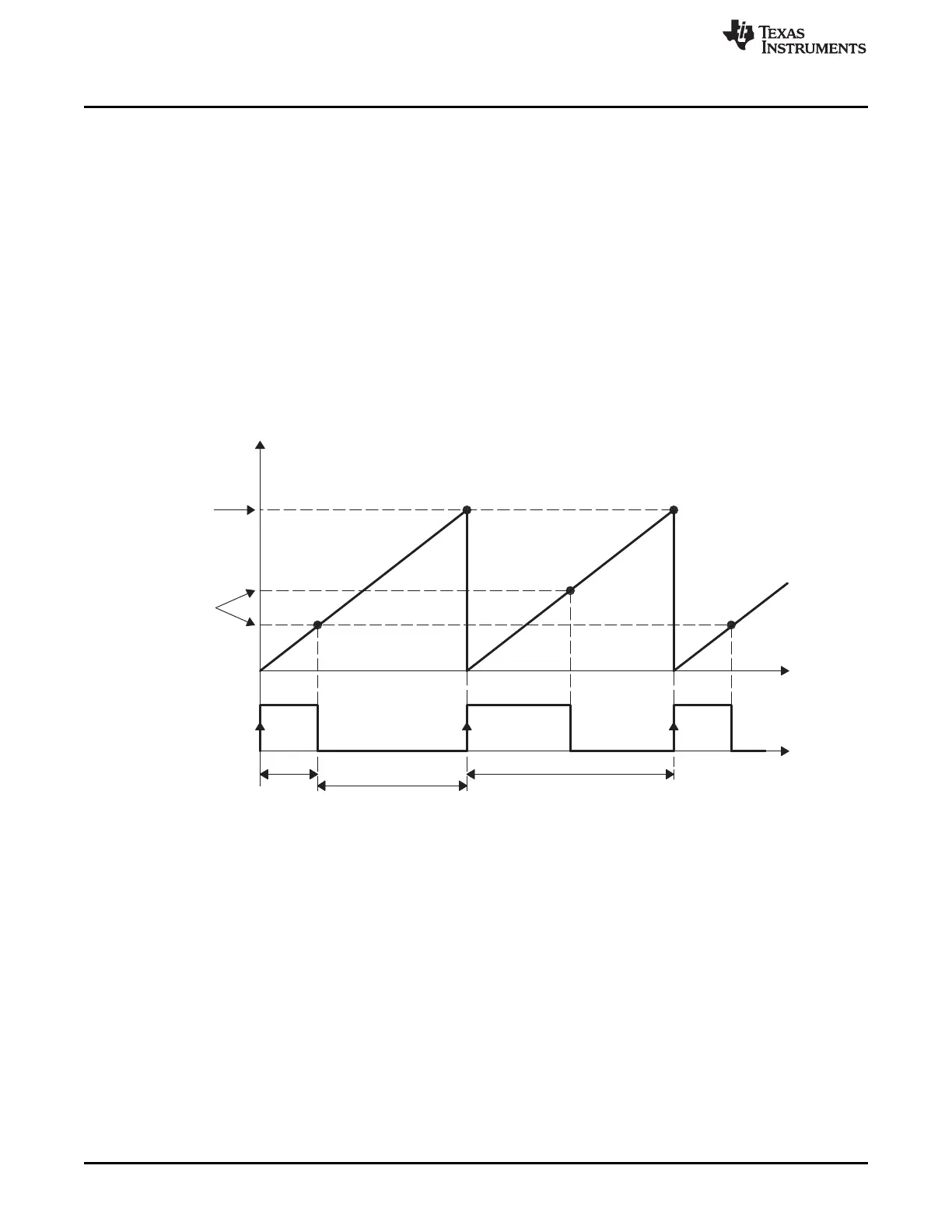
APRD
TSCTR
FFFFFFFF
ACMP
0000000C
APWMx
(o/p pin)
On
time
Off−time
Period
1000h
500h
300h
Enhanced Capture (eCAP) Module
www.ti.com
15.3.2.2.8 APWM Mode Operation
Main operating highlights of the APWM section:
• The time-stamp counter bus is made available for comparison via 2 digital (32-bit) comparators.
• When CAP1/2 registers are not used in capture mode, their contents can be used as Period and
Compare values in APWM mode.
• Double buffering is achieved via shadow registers APRD and ACMP (CAP3/4). The shadow register
contents are transferred over to CAP1/2 registers either immediately upon a write, or on a PRDEQ
trigger.
• In APWM mode, writing to CAP1/CAP2 active registers will also write the same value to the
corresponding shadow registers CAP3/CAP4. This emulates immediate mode. Writing to the shadow
registers CAP3/CAP4 will invoke the shadow mode.
• During initialization, you must write to the active registers for both period and compare. This
automatically copies the initial values into the shadow values. For subsequent compare updates,
during run-time, you only need to use the shadow registers.
Figure 15-108. PWM Waveform Details Of APWM Mode Operation
The behavior of APWM active-high mode (APWMPOL == 0) is:
CMP = 0x00000000, output low for duration of period (0% duty)
CMP = 0x00000001, output high 1 cycle
CMP = 0x00000002, output high 2 cycles
CMP = PERIOD, output high except for 1 cycle (<100% duty)
CMP = PERIOD+1, output high for complete period (100% duty)
CMP > PERIOD+1, output high for complete period
The behavior of APWM active-low mode (APWMPOL == 1) is:
CMP = 0x00000000, output high for duration of period (0% duty)
CMP = 0x00000001, output low 1 cycle
CMP = 0x00000002, output low 2 cycles
CMP = PERIOD, output low except for 1 cycle (<100% duty)
CMP = PERIOD+1, output low for complete period (100% duty)
1616
Pulse-Width Modulation Subsystem (PWMSS) SPRUH73H–October 2011–Revised April 2013
Submit Documentation Feedback
Copyright © 2011–2013, Texas Instruments Incorporated
 Loading...


