www.ti.com
Ethernet Subsystem Registers
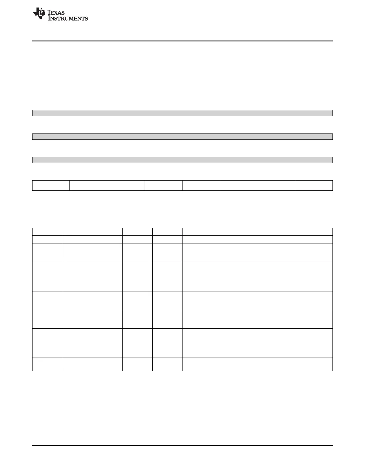
14.5.9.35 RGMII_CTL Register (offset = 88h) [reset = 0h]
RGMII_CTL is shown in Figure 14-231 and described in Table 14-249.
RGMII CONTROL SIGNAL REGISTER
NOTE: This register only has context in RGMII in-band mode. This register is not updated during forced
mode of operation. Note that in-band mode is selected via MACCONTROL.EXT_EN.
Figure 14-231. RGMII_CTL Register
31 30 29 28 27 26 25 24
Reserved
R-0h
23 22 21 20 19 18 17 16
Reserved
R-0h
15 14 13 12 11 10 9 8
Reserved
R-0h
7 6 5 4 3 2 1 0
RGMII2_FULLDUPLE RGMII2_SPEED RGMII2_LINK RGMII1_FULLDUPLE RGMII1_SPEED RGMII1_LINK
X X
R-0h R-0h R-0h R-0h R-0h R-0h
LEGEND: R/W = Read/Write; R = Read only; W1toCl = Write 1 to clear bit; -n = value after reset
Table 14-249. RGMII_CTL Register Field Descriptions
Bit Field Type Reset Description
31-8 Reserved R 0h
7 RGMII2_FULLDUPLEX R 0h RGMII 2 Fullduplex - This is the CPRGMII fullduplex output signal.
0 - Half-duplex mode
1 - Fullduplex mode
6-5 RGMII2_SPEED R 0h RGMII2 Speed - This is the CPRGMI speed output signal
00 - 10Mbps mode
01 - 100Mbps mode
10 - 1000Mbps (gig) mode
11 - reserved
4 RGMII2_LINK R 0h RGMII2 Link Indicator - This is the CPRGMII link output signal
0 - RGMII2 link is down
1 - RGMII2 link is up
3 RGMII1_FULLDUPLEX R 0h RGMII1 Fullduplex - This is the CPRGMII fullduplex output signal.
0 - Half-duplex mode
1 - Fullduplex mode
2-1 RGMII1_SPEED R 0h RGMII1 Speed - This is the CPRGMII speed output signal
00 - 10Mbps mode
01 - 100Mbps mode
10 - 1000Mbps (gig) mode
11 - reserved
0 RGMII1_LINK R 0h RGMII1 Link Indicator - This is the CPRGMII link output signal
0 - RGMII1 link is down
14.5.10 Management Data Input/Output (MDIO) Registers
This section describes the memory-mapped registers for the Management Data Input/Output (MDIO).
Table 14-250 lists the memory-mapped registers for the Management Data Input/Output (MDIO). See the
device-specific data manual for the memory address of these registers.
1473
SPRUH73H–October 2011–Revised April 2013 Ethernet Subsystem
Submit Documentation Feedback
Copyright © 2011–2013, Texas Instruments Incorporated

 Loading...


