ArrayBCNTArray2Array1Frame0
ACNTbytesin
Array/1stdimension
Array1
Frame1 ArrayBCNT
Array1FrameCCNT ArrayBCNTArray2
CCNTframesin
Block/3rddimmension
BCNTarraysinFrame/2nddimmension
Array2
www.ti.com
Functional Description
When the EDMA3TC is idle and receives its first TR, DMA program register set receives the TR, where it
transitions to the DMA source active set and the destination FIFO register set immediately. The second
TR (if pending from EDMA3CC) is loaded into the DMA program set, ensuring it can start as soon as
possible when the active transfer completes. As soon as the current active set is exhausted, the TR is
loaded from the DMA program register set into the DMA source active register set as well as to the
appropriate entry in the destination FIFO register set.
The read controller issues read commands governed by the rules of command fragmentation and
optimization. These are issued only when the data FIFO has space available for the data read. When
sufficient data is in the data FIFO, the write controller starts issuing a write command again following the
rules for command fragmentation and optimization. For more information on command fragmentation and
optimization, refer to Section 11.3.12.1.1.
Depending on the number of entries, the read controller can process up to two or four transfer requests
ahead of the destination subject to the amount of free data FIFO.
11.3.2 Types of EDMA3 Transfers
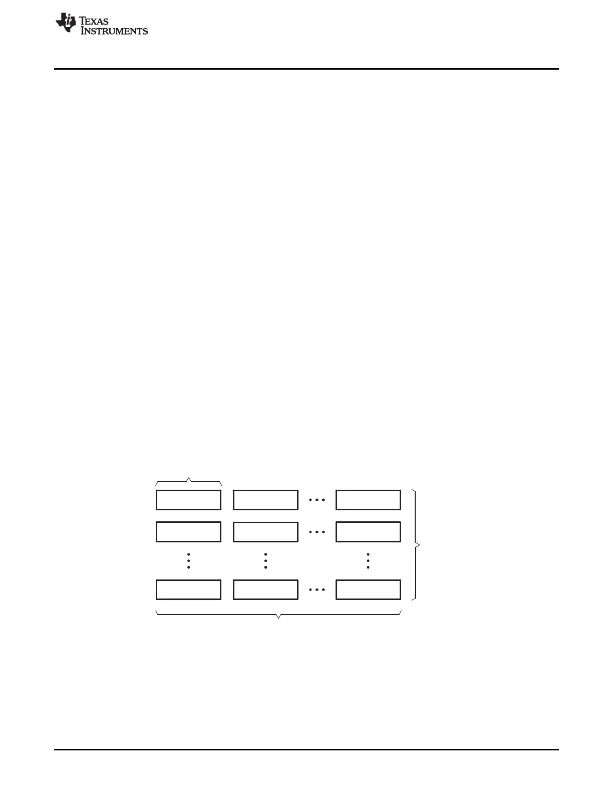
An EDMA3 transfer is always defined in terms of three dimensions. Figure 11-6 shows the three
dimensions used by EDMA3 transfers. These three dimensions are defined as:
• 1st Dimension or Array (A): The 1st dimension in a transfer consists of ACNT contiguous bytes.
• 2nd Dimension or Frame (B): The 2nd dimension in a transfer consists of BCNT arrays of ACNT bytes.
Each array transfer in the 2nd dimension is separated from each other by an index programmed using
SRCBIDX or DSTBIDX.
• 3rd Dimension or Block (C): The 3rd dimension in a transfer consists of CCNT frames of BCNT arrays
of ACNT bytes. Each transfer in the 3rd dimension is separated from the previous by an index
programmed using SRCCIDX or DSTCIDX.
Note that the reference point for the index depends on the synchronization type. The amount of data
transferred upon receipt of a trigger/synchronization event is controlled by the synchronization types
(SYNCDIM bit in OPT). Of the three dimensions, only two synchronization types are supported: A-
synchronized transfers and AB-synchronized transfers.
Figure 11-6. Definition of ACNT, BCNT, and CCNT
879
SPRUH73H–October 2011–Revised April 2013 Enhanced Direct Memory Access (EDMA)
Submit Documentation Feedback
Copyright © 2011–2013, Texas Instruments Incorporated

 Loading...


