ARM Cortex-A8 MPU Subsystem
www.ti.com
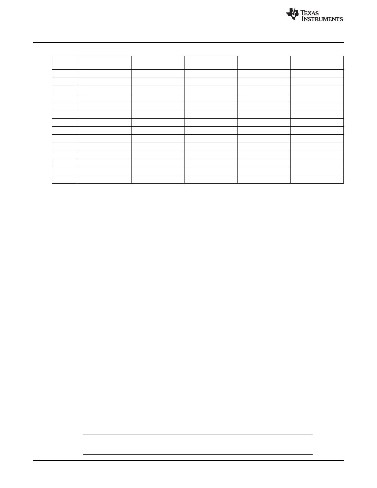
Table 3-6. MPU Subsystem Operation Power Modes
Mode MPU and ARM Core ARM L2 RAM NEON INTC Device Core and APB/ATB Debug
Logic ETM
1 Active Active Active Active Disabled or enabled
2 Active Active OFF Active Disabled or enabled
3 Active RET Active Active Disabled or enabled
4 Active RET OFF Active Disabled or enabled
5 Active OFF Active Active Disabled or enabled
6 Active OFF OFF Active Disabled or enabled
7 OFF RET OFF OFF Disabled or enabled
8 Standby Active Standby Active Disabled or enabled
9 Standby Active OFF Active Disabled or enabled
10 Standby RET Standby Active Disabled or enabled
11 Standby RET OFF Active Disabled or enabled
12 Standby OFF Standby Active Disabled or enabled
13 Standby OFF OFF Active Disabled or enabled
14 OFF OFF OFF OFF Disabled or enabled
3.1.7 ARM Programming Model
For detailed descriptions of registers used for MPU configuration, see Chapter 8, Power, Reset, and Clock
Management (PRCM).
3.1.7.1 Clock Control
For clock configuration settings, see Chapter 8, Power, Reset, and Clock Management (PRCM).
3.1.7.2 MPU Power Mode Transitions
The following subsections describe transitions of different power modes for MPU power domain:
• Basic power on reset
• MPU into standby mode
• MPU out of standby mode
• MPU power on from a powered off state
3.1.7.2.1 Basic Power-On Reset
The power-on reset follows the following sequence of operation and is applicable to initial power-up and
wakeup from device off mode:
Reset the INTC (CORE_RST) and the MPU subsystem modules (MPU_RST). The clocks must be
active during the MPU reset and CORE reset.
3.1.7.2.2 MPU Into Standby Mode
The MPU into standby mode follows the following sequence of operation and is applicable to initial power-
up and wakeup from device Off mode.
1. The ARM core initiates entering into standby via software only (CP15 - WFI).
2. MPU modules requested internally of MPU subsystem to enter idle, after ARM core standby detected.
3. MPU is in standby output asserted for PRCM (all outputs guaranteed to be at reset values).
4. PRCM can now request INTC to enter into idle mode. Acknowledge from INTC goes to PRCM.
NOTE: The INTC SWAKEUP output is a pure hardware signal to PRCM for the status of its IDLE
request and IDLE acknowledge handshake.
174
ARM MPU Subsystem SPRUH73H–October 2011–Revised April 2013
Submit Documentation Feedback
Copyright © 2011–2013, Texas Instruments Incorporated

 Loading...


