1
7 n 7 n
1 1 1 1 1 1 1 1
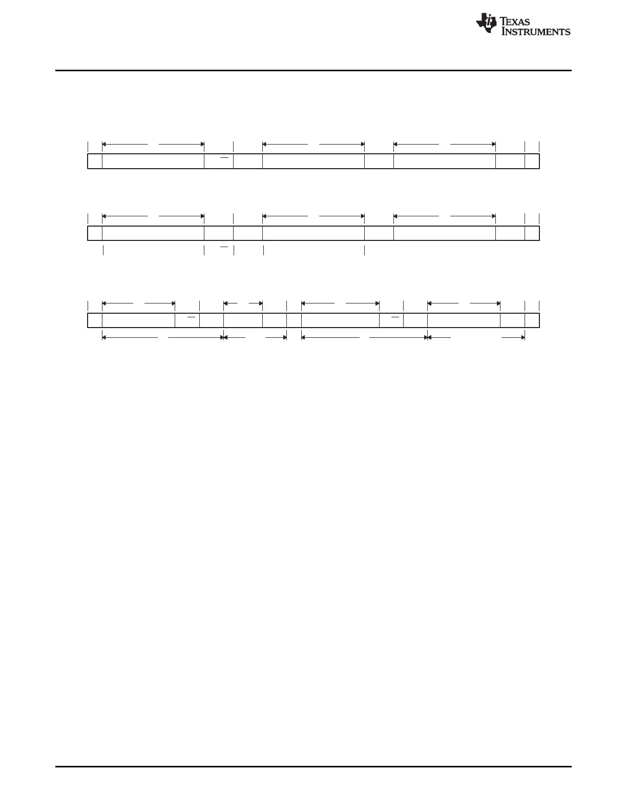
S Slave address
R/W
ACK
Data
ACK
S Slave address
R/W ACK
Data
ACK
P
1 Any
number
1 Any number
S
1
1 1 1 1 0 A A
7
A A A A A A A AACK0
11
8
ACK
1
Data
n
ACK
1
P
1
A A = 2 MSBs R/W 8 LSBs of slave address
S Slave address R/W ACK Data ACK Data ACK P
7 n n
1 1 1 1 1 1
Functional Description
www.ti.com
The least significant R/nW of the address byte indicates the direction of transmission of the following data
bytes. If R/nW is 0, the master writes data into the selected slave; if it is 1, the master reads data out of
the slave.
Figure 21-8. I2C Data Transfer Formats
7-Bit Addressing Format
10-Bit Addressing Format
7-Bit Addressing Format With Repeated START Condition
21.3.6.2 Master Transmitter
In this mode, data assembled in one of the previously described data formats is shifted out on the serial
data line SDA in synch with the self-generated clock pulses on the serial clock line SCL. The clock pulses
are inhibited and SCL held low when the intervention of the processor is required (XUDF) after a byte has
been transmitted.
21.3.6.3 Master Receiver
This mode can only be entered from the master transmitter mode. With either of the address formats
(Figure 21-8 (a), (b), and (c)), the master receiver is entered after the slave address byte and bit R/W_
has been transmitted, if R/W_ is high. Serial data bits received on bus line SDA are shifted in synch with
the self-generated clock pulses on SCL. The clock pulses are inhibited and SCL held low when the
intervention of the processor is required (ROVR) after a byte has been transmitted. At the end of a
transfer, it generates the stop condition.
21.3.6.4 Slave Transmitter
This mode can only be entered from the slave receiver mode. With either of the address formats
(Figure 21-8 (a), (b), and (c)), the slave transmitter is entered if the slave address byte is the same as its
own address and bit R/W_ has been transmitted, if R/W_ is high. The slave transmitter shifts the serial
data out on the data line SDA in synch with the clock pulses that are generated by the master device. It
does not generate the clock but it can hold clock line SCL low while intervention of the CPU is required
(XUDF).
21.3.6.5 Slave Receiver
In this mode, serial data bits received on the bus line SDA are shifted-in in synch with the clock pulses on
SCL that are generated by the master device. It does not generate the clock but it can hold clock line SCL
low while intervention of the CPU is required (ROVR) following the reception of a byte.
3706
I2C SPRUH73H–October 2011–Revised April 2013
Submit Documentation Feedback
Copyright © 2011–2013, Texas Instruments Incorporated

 Loading...


