www.ti.com
Touchscreen Controller Registers
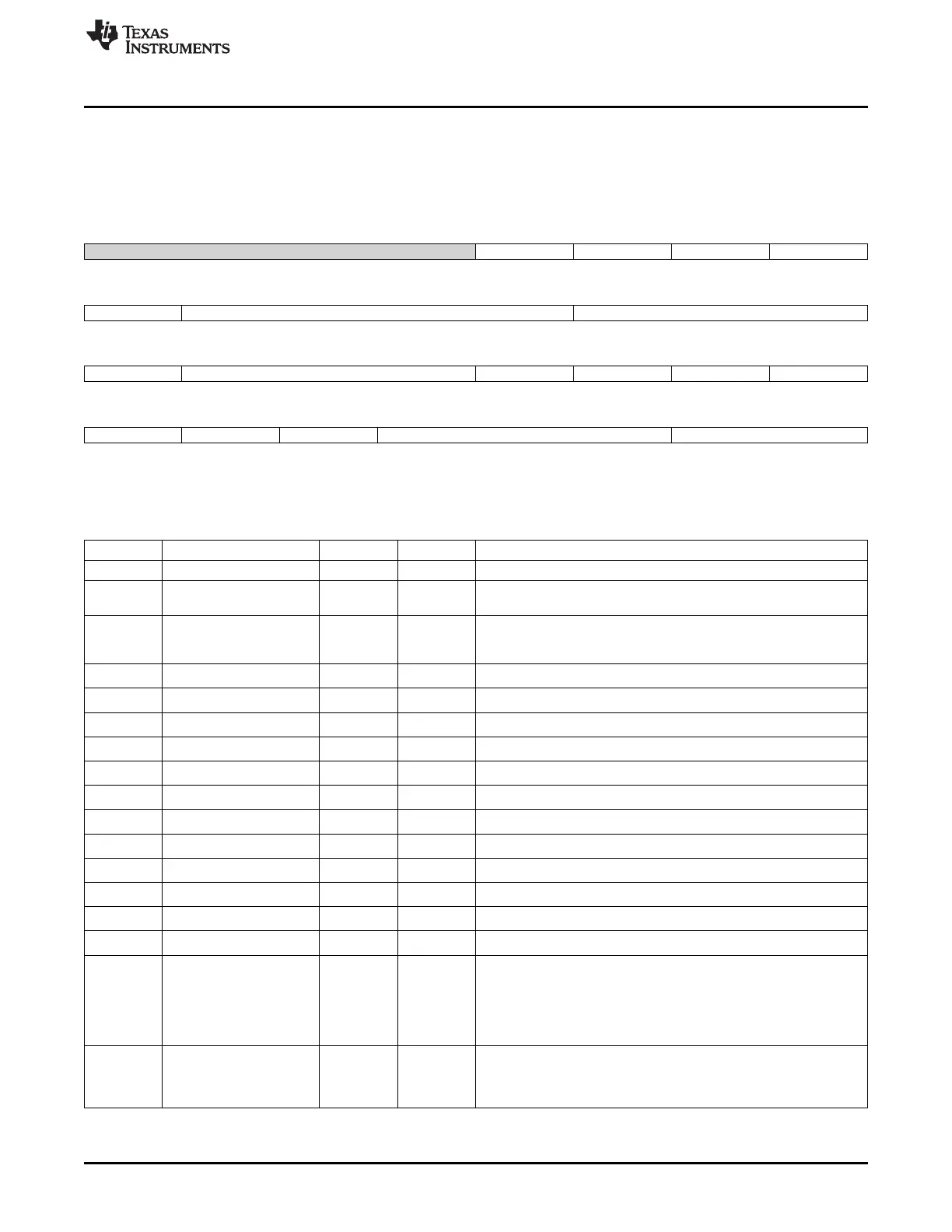
12.5.1.23 STEPCONFIG3 Register (offset = 74h) [reset = 0h]
STEPCONFIG3 is shown in Figure 12-27 and described in Table 12-27.
Step Configuration 3
Figure 12-27. STEPCONFIG3 Register
31 30 29 28 27 26 25 24
Reserved Range_check FIFO_select Diff_CNTRL SEL_RFM_SWC_1_0
R/W-0h R/W-0h R/W-0h R/W-0h R/W-0h
23 22 21 20 19 18 17 16
SEL_RFM_SWC_1_0 SEL_INP_SWC_3_0 SEL_INM_SWC_3_0
R/W-0h R/W-0h R/W-0h
15 14 13 12 11 10 9 8
SEL_INM_SWC_3_0 SEL_RFP_SWC_2_0 WPNSW_SWC YPNSW_SWC XNPSW_SWC YNNSW_SWC
R/W-0h R/W-0h R/W-0h R/W-0h R/W-0h R/W-0h
7 6 5 4 3 2 1 0
YPPSW_SWC XNNSW_SWC XPPSW_SWC Averaging Mode
R/W-0h R/W-0h R/W-0h R/W-0h R/W-0h
LEGEND: R/W = Read/Write; R = Read only; W1toCl = Write 1 to clear bit; -n = value after reset
Table 12-27. STEPCONFIG3 Register Field Descriptions
Bit Field Type Reset Description
31-28 Reserved R/W 0h
27 Range_check R/W 0h 0 = Disable out-of-range check.
1 = Compare ADC data with range check register.
26 FIFO_select R/W 0h Sampled data will be stored in FIFO.
0 = FIFO.
1 = FIFO1.
25 Diff_CNTRL R/W 0h
Differential Control Pin
24-23 SEL_RFM_SWC_1_0 R/W 0h
SEL_RFM pins SW configuration
22-19 SEL_INP_SWC_3_0 R/W 0h
SEL_INP pins SW configuration
18-15 SEL_INM_SWC_3_0 R/W 0h
SEL_INM pins for negative differential
14-12 SEL_RFP_SWC_2_0 R/W 0h
SEL_RFP pins SW configuration
11 WPNSW_SWC R/W 0h
WPNSW pin SW configuration
10 YPNSW_SWC R/W 0h
YPNSW pin SW configuration
9 XNPSW_SWC R/W 0h
XNPSW pin SW configuration
8 YNNSW_SWC R/W 0h
YNNSW pin SW configuration
7 YPPSW_SWC R/W 0h
YPPSW pin SW configuration
6 XNNSW_SWC R/W 0h
XNNSW pin SW configuration
5 XPPSW_SWC R/W 0h
XPPSW pin SW configuration
4-2 Averaging R/W 0h Number of samples to average:
000 = No average.
001 = 2 samples average.
010 = 4 samples average.
011 = 8 samples average.
100 = 16 samples average.
1-0 Mode R/W 0h 00 = SW enabled, one-shot.
01 = SW enabled, continuous.
10 = HW synchronized, one-shot.
11 = HW synchronized, continuous.
1061
SPRUH73H–October 2011–Revised April 2013 Touchscreen Controller
Submit Documentation Feedback
Copyright © 2011–2013, Texas Instruments Incorporated

 Loading...


