LCD Registers
www.ti.com
13.5.12 RASTER_TIMING_1 Register (offset = 30h) [reset = 0h]
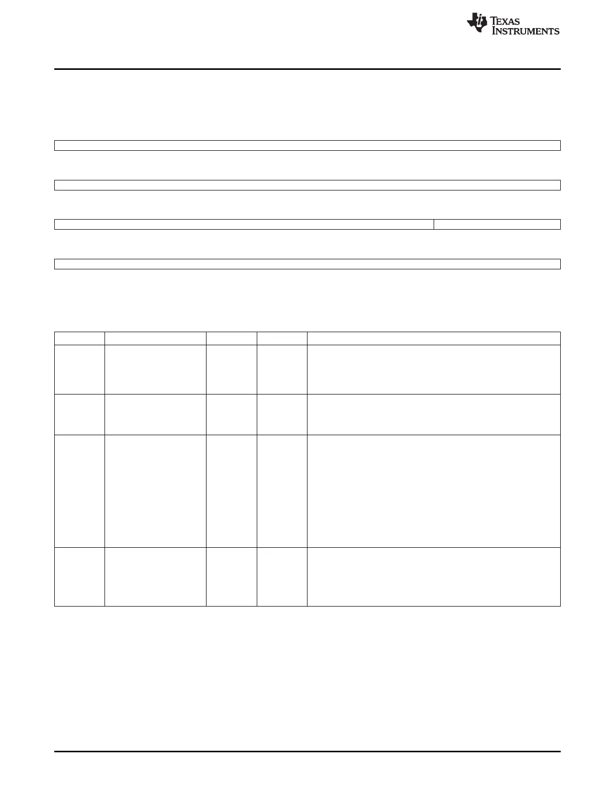
RASTER_TIMING_1 is shown in Figure 13-30 and described in Table 13-25.
Figure 13-30. RASTER_TIMING_1 Register
31 30 29 28 27 26 25 24
vbp
R/W-0h
23 22 21 20 19 18 17 16
vfp
R/W-0h
15 14 13 12 11 10 9 8
vsw lpp
R/W-0h R/W-0h
7 6 5 4 3 2 1 0
lpp
R/W-0h
LEGEND: R/W = Read/Write; R = Read only; W1toCl = Write 1 to clear bit; -n = value after reset
Table 13-25. RASTER_TIMING_1 Register Field Descriptions
Bit Field Type Reset Description
31-24 vbp R/W 0h Vertical Back Porch Value (from 0-255) use to specify the number of
line clock periods to add to the beginning of a frame before the first
set of pixels is output to the display
Note that line clock transitions during the insertion of the extra line
clock periods
23-16 vfp R/W 0h Vertical Front Porch Value (from 0-255) used to specify the number
of line clock periods to add to the end of each frame
Note that the line clock transitions during the insertion of the extra
line clock periods
15-10 vsw R/W 0h Vertical Sync Width Pulse In active mode (lcdtft=1), encoded value
(from 1-64) used to specify the number of line clock periods to set
the lcd_fp pin active at the end of each frame after the (vfp) period
elapses
The number of clock cycles is programmed value plus one
The frame clock is used as the VSYNC signal in active mode
In passive mode (lcdtft=0), encoded value (from 1-64) used to
specify the number of extra line clock periods to insert after the
vertical front porch (vfp) period has elapsed
Note that the width of lcd_fp is not affected by vsw in passive mode
and line clock transitions during the insertion of the extra line clock
periods (programmed value plus one)
9-0 lpp R/W 0h Lines Per Panel Encoded value (programmed value range of
{0:2047} represents an actual range of {1:2048}) used to specify the
number of lines per panel
It represents the total number of lines on the LCD (programmed
value plus one)
Bit 10 of this field is in RASTER_TIMING_2
1142
LCD Controller SPRUH73H–October 2011–Revised April 2013
Submit Documentation Feedback
Copyright © 2011–2013, Texas Instruments Incorporated

 Loading...


