www.ti.com
UART Registers
19.5.1.10 Line Control Register (LCR)
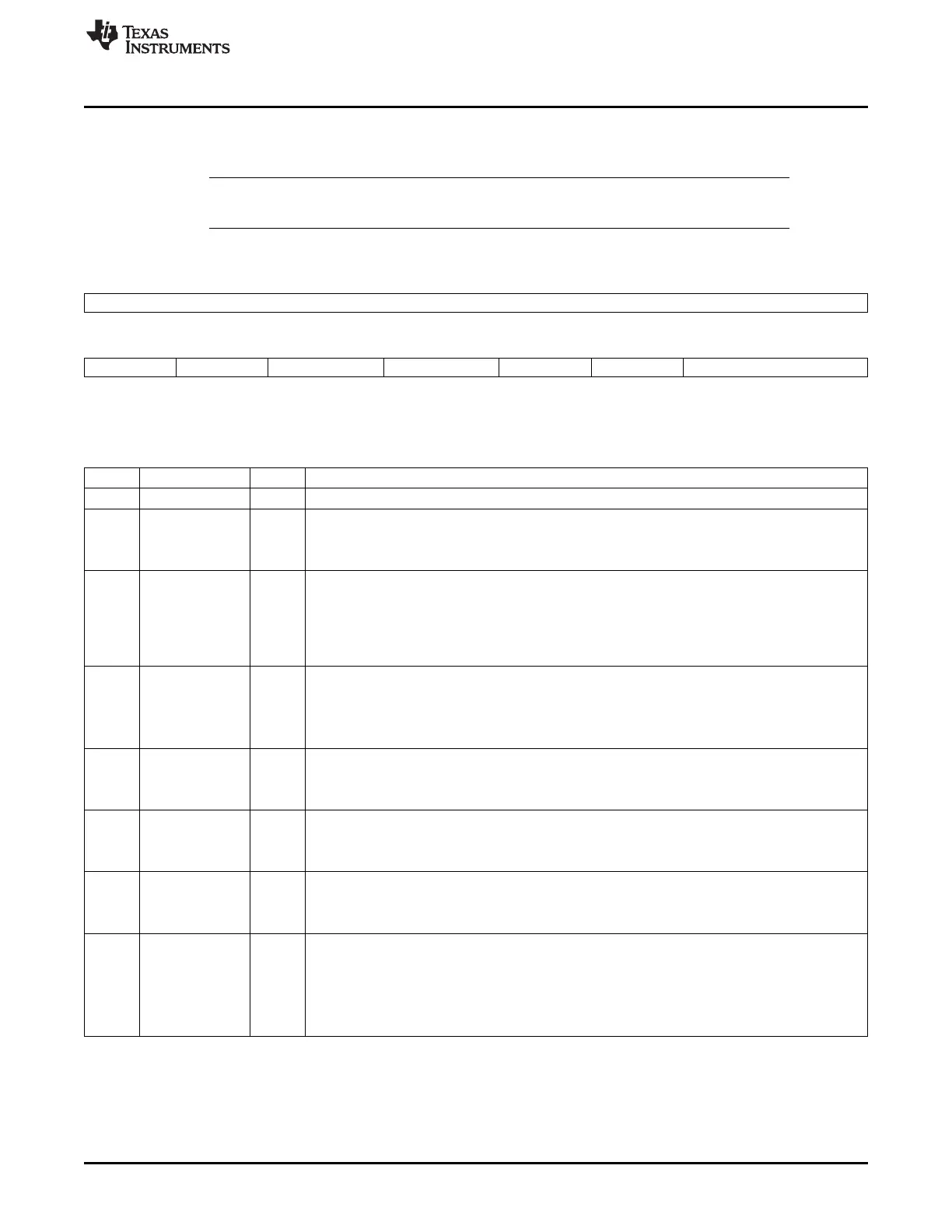
The line control register (LCR) is shown in Figure 19-43 and described in Table 19-39.
NOTE: As soon as LCR[6] is set to 1, the TX line is forced to 0 and remains in this state as long as
LCR[6] = 1.
Figure 19-43. Line Control Register (LCR)
15 8
Reserved
R-0
7 6 5 4 3 2 1 0
DIV_EN BREAK_EN PARITY_TYPE2 PARITY_TYPE1 PARITY_EN NB_STOP CHAR_LENGTH
R/W-0 R/W-0 R/W-0 R/W-0 R/W-0 R/W-0 R/W-0
LEGEND: R/W = Read/Write; R = Read only; -n = value after reset
Table 19-39. Line Control Register (LCR) Field Descriptions
Bit Field Value Description
15-8 Reserved 0 Reserved.
7 DIV_EN Divisor latch enable.
0 Normal operating condition.
1 Divisor latch enable. Allows access to DLL and DLH.
6 BREAK_EN Break control bit.
Note: When LCR[6] is set to 1, the TX line is forced to 0 and remains in this state as long as
LCR[6] = 1.
0 Normal operating condition.
1 Forces the transmitter output to go low to alert the communication terminal.
5 PARITY_TYPE2 If LCR[3] = 1:
0 If LCR[5] = 0, LCR[4] selects the forced parity format.
1 If LCR[5] = 1 and LCR[4] = 0, the parity bit is forced to 1 in the transmitted and received data.
1 If LCR[5] = 1 and LCR[4] = 1, the parity bit is forced to 0 in the transmitted and received data.
4 PARITY_TYPE1 If LCR[3] = 1:
0 Odd parity is generated.
1 Even parity is generated.
3 PARITY_EN Parity bit.
0 No parity.
1 A parity bit is generated during transmission, and the receiver checks for received parity.
2 NB_STOP Specifies the number of stop bits.
0 1 stop bit (word length = 5, 6, 7, 8).
1 1.5 stop bits (word length = 5) or 2 stop bits (word length = 6, 7, 8).
1-0 CHAR_LENGTH 0-3h Specifies the word length to be transmitted or received.
0 5 bits
1h 6 bits
2h 7 bits
3h 8 bit
3515
SPRUH73H–October 2011–Revised April 2013 Universal Asynchronous Receiver/Transmitter (UART)
Submit Documentation Feedback
Copyright © 2011–2013, Texas Instruments Incorporated

 Loading...


