www.ti.com
Integration
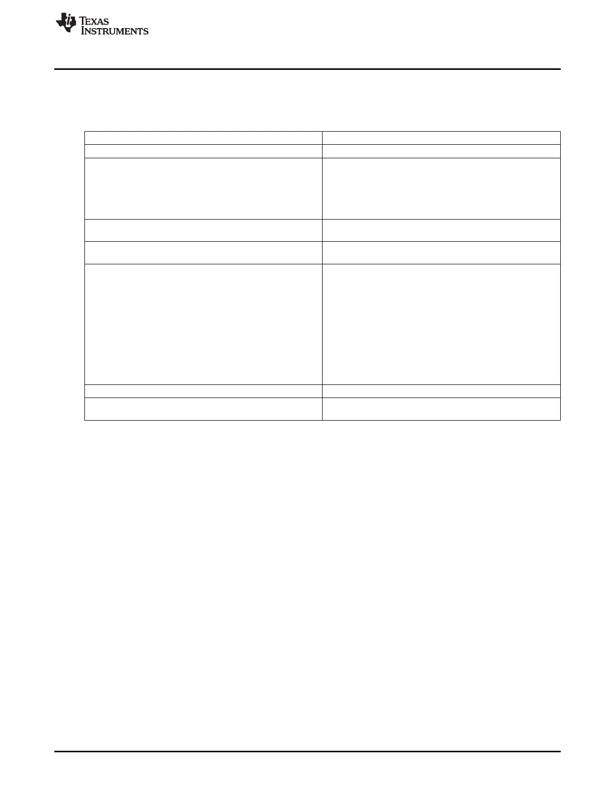
14.2.1 Ethernet Switch Connectivity Attributes
The general connectivity attributes for the Ethernet Switch module are shown in Table 14-2.
Table 14-2. Ethernet Switch Connectivity Attributes
Attributes Type
Power Domain Peripheral Domain
Clock Domain
PD_PER_CPSW_125MHZ_GCLK (Main)
PD_PER_CPSW_250MHZ_GCLK (MHZ_250_CLK)
PD_PER_CPSW_50MHZ_GCLK (MHZ_50_CLK)
PD_PER_CPSW_5MHZ_GCLK (MHZ_5_CLK)
PD_PER_CPSW_CPTS_RFT_CLK (CPTS_RFT_CLK)
Reset Signals CPSW_MAIN_ARST_N
CPSW_ISO_MAIN_ARST_N
Idle/Wakeup Signals Idle
Standby
Interrupt Requests
4 Interrupts
RX_THRESH (3PGSWRXTHR0) – Receive Threshold interrupt
(nonpaced)
RX (3PGSWRXINT0) – Receive interrupt (paced)
TX (3PGSWTXINT0) – Transmit interrupt (paced)
Misc (3PGSWMISC0) – Other interrupts
All Ethernet Switch interrupts go to MPU Subsystem and PRU-
ICSS.
The Subsystem contains 3 sets of interrupts C0, C1, and C2 to
allow for split core processing of packets. On this device, only
the C0 version of the interrupts is used.
DMA Requests None
Physical Address L4 Fast slave port
L3 Fast initiator port
1167
SPRUH73H–October 2011–Revised April 2013 Ethernet Subsystem
Submit Documentation Feedback
Copyright © 2011–2013, Texas Instruments Incorporated

 Loading...


