Booting
Process next device
Process device
No more devices in the list
Memory
Booting
Peripheral
Booting
Device is of peripheral type
Device is of memory type
-Fail
-Timeout
Fail
Set the booting device list based on
the SW Booting Configuration or
SYSBOOT pins
No
Yes
Last device in the list?Get next device in the list
Jump to Initial SW
Success Success
Dead loop
www.ti.com
Functional Description
Table 26-6 summarizes the ROM Code default settings for clocks. This default configuration enables all
the ROM Code functionalities with minimized needs on power during boot.
Table 26-6. ROM Code Default Clock Settings
Clock Frequency [MHz] Source
L3F_CLK 200 CORE_CLKOUTM4
SPI_CLK 48 PER_CLKOUTM2
MMC_CLK 96 PER_CLKOUTM2
UART_CLK 48 PER_CLKOUTM2
I2C_CLK 48 PER_CLKOUTM2
MPU_CLK 500 MPU_PLL
USB_PHY_CLK 960 MHz PER_CLKDCOLDO
The DPLLs and PRCM clock dividers are configured with the ROM Code default values after cold or warm
reset in order to give the same working conditions to the Public ROM Code sequence.
26.1.5 Booting
26.1.5.1 Overview
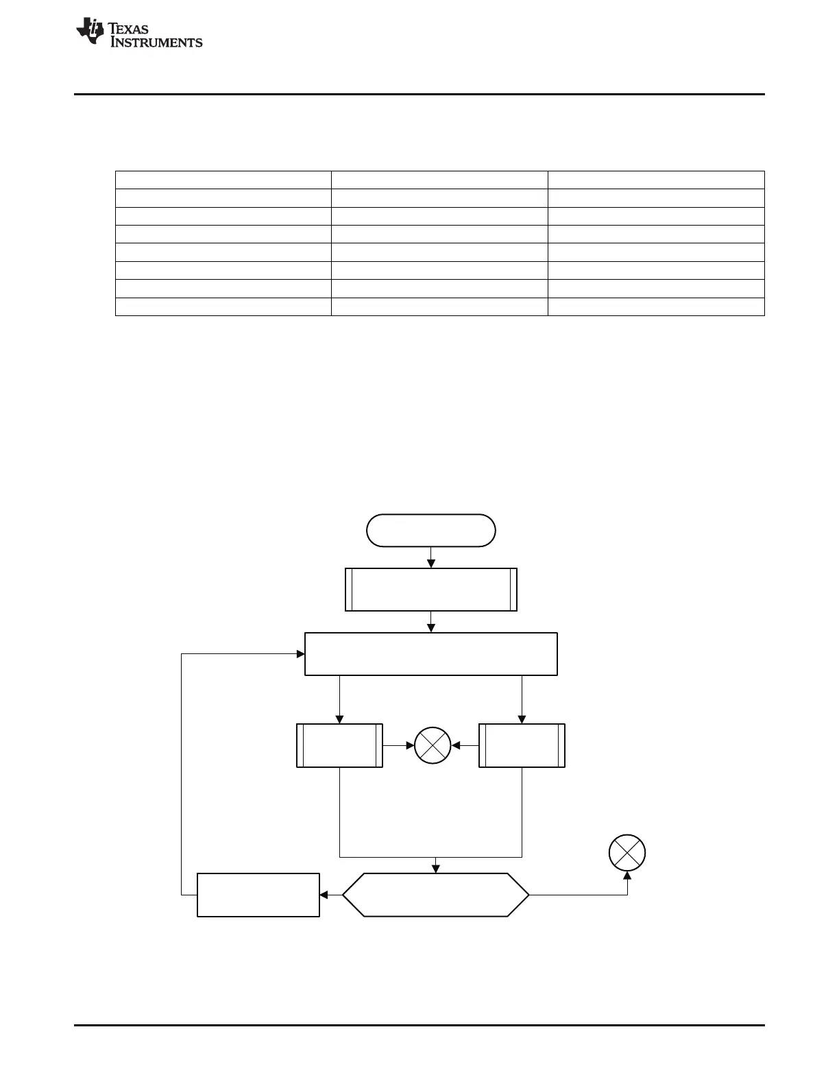
Figure 26-6 shows the booting procedure. First a booting device list is created. The list consists of all
devices which will be searched for a booting image. The list is filled in based on the SYSBOOT.
Figure 26-6. ROM Code Booting Procedure
Once the booting device list is set up, the booting routine examines the devices enumerated in the list
sequentially and either executes the memory booting or peripheral booting procedure depending on the
booting device type. The memory booting procedure is executed when the booting device type is one of
NOR, NAND, MMC or SPI-EEPROM. The peripheral booting is executed when the booting device type is
Ethernet, USB or UART.
4103
SPRUH73H–October 2011–Revised April 2013 Initialization
Submit Documentation Feedback
Copyright © 2011–2013, Texas Instruments Incorporated

 Loading...


