Integration
www.ti.com
22.2.2 McASP Clock and Reset Management
The McASP module uses functional clocks either generated internally (master mode) or supplied from its
serial interface (slave mode). The internal interconnect interface clock is used for the module internal OCP
interface. Internal registers select the source of the functional clocks and the applied divider ratio.
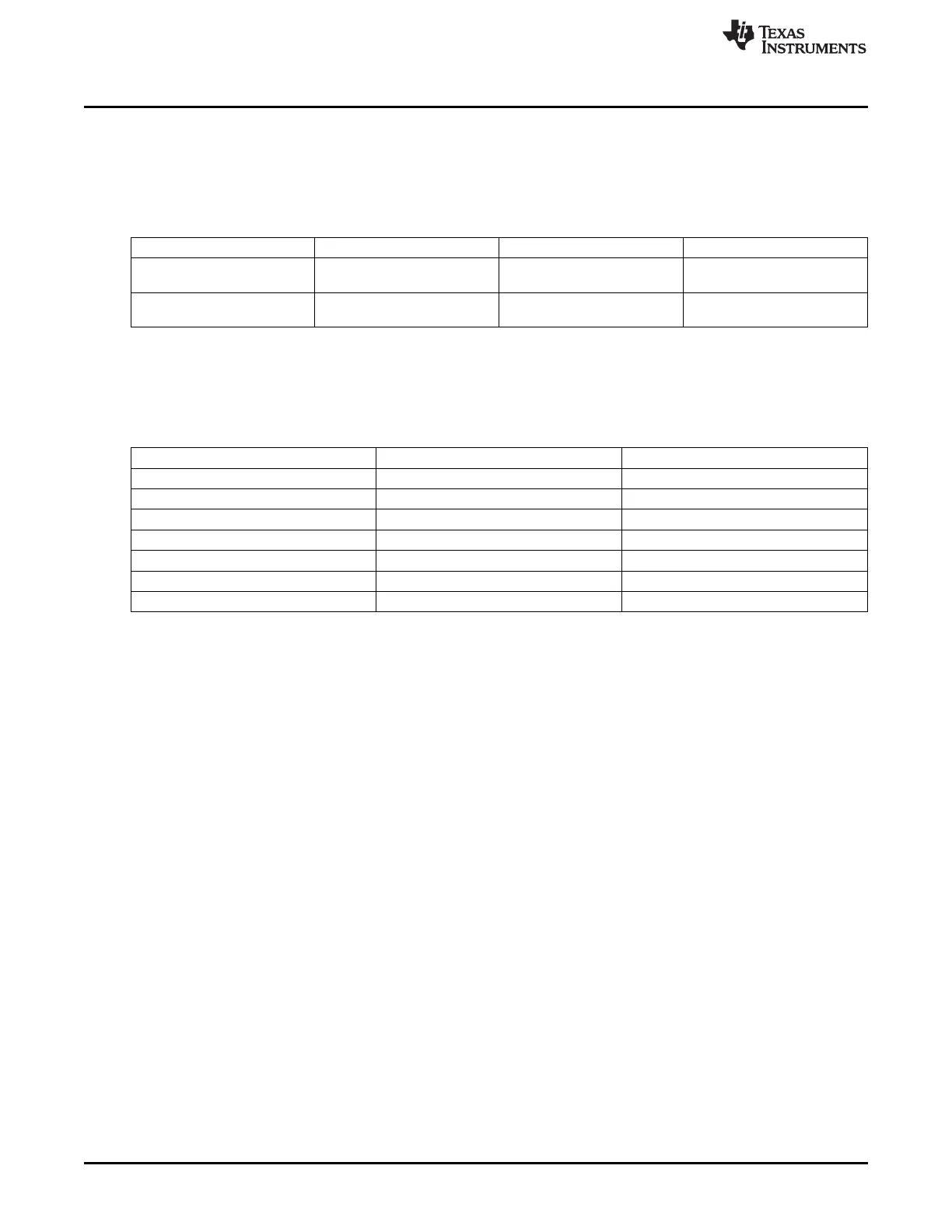
Table 22-2. McASP Clock Signals
Clock Signal Max Freq Reference / Source Comments
ocp_clk 100 MHz CORE_CLKOUTM4 / 2 pd_per_l3s_gclk
Interface clock From PRCM
auxclk 26 MHz CLK_M_OSC pd_per_mcasp_fclk
Functional clock From PRCM
22.2.3 McASP Pin List
The McASP external interface signals are shown in Table 22-3.
Table 22-3. McASP Pin List
Pin Type Description
McASPx_AXR[3:0] I/O Audio transmit/receive pin
McASPx_ACLKX
(1)
I/O Transmit clock
McASPx_FSX
(1)
I/O Frame synch for transmit
McASPx_AHCLKX
(1)
I/O High speed transmit clock
McASPx_ACLKR
(1)
I/O Receive clock
McASPx_FSR
(1)
I/O Frame synch for receive
McASPx_AHCLKR
(1)
I/O High speed receive clock
(1)
These signals are also used as inputs to re-time or sync data. The associated CONF_<module>_<pin>_RXACTIVE bit for these
signals must be set to 1 to enable the inputs back to the module. It is also recommended to place a 33-ohm resistor in series
(close to the processor) on each of these signals to avoid signal reflections.
3772
Multichannel Audio Serial Port (McASP) SPRUH73H–October 2011–Revised April 2013
Submit Documentation Feedback
Copyright © 2011–2013, Texas Instruments Incorporated

 Loading...


