CONTROL_MODULE Registers
www.ti.com
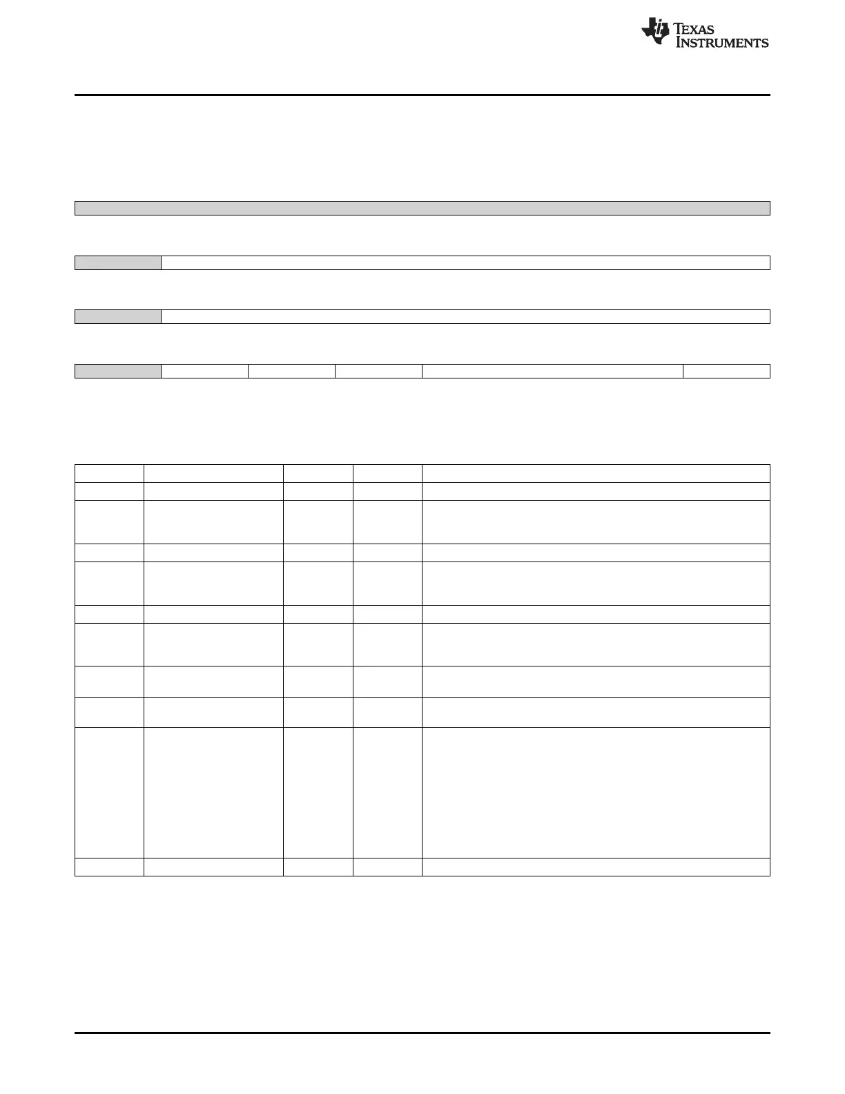
9.3.54 vtp_ctrl Register (offset = E0Ch) [reset = 0h]
vtp_ctrl is shown in Figure 9-57 and described in Table 9-64.
Figure 9-57. vtp_ctrl Register
31 30 29 28 27 26 25 24
Reserved
R-0h
23 22 21 20 19 18 17 16
Reserved pcin
R-0h R-0h
15 14 13 12 11 10 9 8
Reserved ncin
R-0h R-0h
7 6 5 4 3 2 1 0
Reserved enable ready lock filter clrz
R-0h R/W-0h R-0h R/W-0h R/W-0h R/W-0h
LEGEND: R/W = Read/Write; R = Read only; W1toCl = Write 1 to clear bit; -n = value after reset
Table 9-64. vtp_ctrl Register Field Descriptions
Bit Field Type Reset Description
31-23 Reserved R 0h
22-16 pcin R 1h Default/reset values of 'P' for the VTP controller.
See "Silicon Revision Functional Differences and Enhancements" for
differences in operation based on AM335x silicon revision.
15 Reserved R 0h
14-8 ncin R 1h Default/reset values of 'N' for the VTP controller.
See "Silicon Revision Functional Differences and Enhancements" for
differences in operation based on AM335x silicon revision.
7 Reserved R 0h
6 enable R/W 0h 0: VTP macro in bypass mode. P and N are driven from PCIN and
NCIN.
1: Dynamic VTP compensation mode
5 ready R 0h 0: Training sequence is not complete
1: Training sequence is complete
4 lock R/W 0h 0: Normal operation dynamic update
1: freeze dynamic update, pwrdn controller
3-1 filter R/W 0h Digital filter bits to prevent the controller from making excessive
number of changes.
000: Filter off
001: Update on two consecutive update requests
010: Update on three consecutive update requests
011: Update on four consecutive update requests
100: Update on five consecutive update requests
101: Update on six consecutive update requests
110: Update on seven consecutive update requests
111: Update on eight consecutive update requests
0 clrz R/W 0h clears flops, start count again, after low going pulse
818
Control Module SPRUH73H–October 2011–Revised April 2013
Submit Documentation Feedback
Copyright © 2011–2013, Texas Instruments Incorporated

 Loading...


