Power, Reset, and Clock Management
www.ti.com
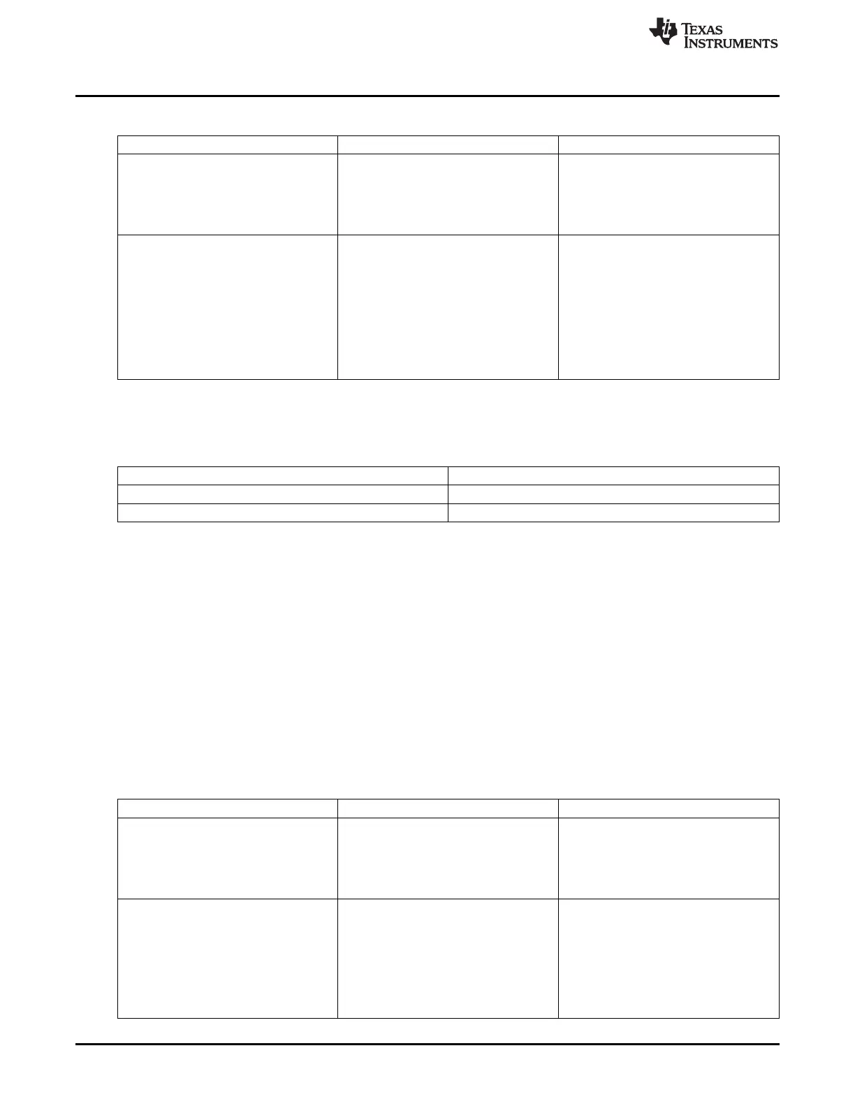
Table 8-1. Master Module Standby-Mode Settings (continued)
Standby Mode Value Selected Mode Description
The module asserts the standby request
based on its internal activity status. The
standby signal is asserted only when all
0x2 Smart-standby
ongoing transactions are complete and
the module is idled. The PRCM module
can then gate the clocks to the module.
The module asserts the standby request
based on its internal activity status. The
standby signal is asserted only when all
ongoing transactions are complete and
the module is idle. The PRCM module can
0x3 Smart-standbywakeup-capable mode then gate the clocks to the module. The
module may generate (master-related)
wake-up events when in STANDBY state.
The mode is relevant only if the
appropriate module mwakeup output is
implemented.
The standby status of a master module is indicated by the
CM_<Power_domain>_<Module>_CLKCTRL[x]. STBYST bit in the PRCM module.
Table 8-2. Master Module Standby Status
STBYST Bit Value Description
0x0 The module is functional.
0x1 The module is in standby mode
8.1.3.2.2 Slave Idle Protocol
This hardware protocol allows the PRCM module to control the state of a slave module. The PRCM
module informs the slave module, through assertion of an idle request, when its clocks (interface and
functional) can be gated. The slave can then acknowledge the request from the PRCM module and the
PRCM module is then allowed to gate the clocks to the module. A slave module is said to be in IDLE state
when its clocks are gated by the PRCM module. Similarly, an idled slave module may need to be
wakened because of a service request from a master module or as a result of an event (called a wake-up
event; for example, interrupt or DMA request) received by the slave module. In this situation the PRCM
module enables the clocks to the module and then deasserts the idle request to signal the module to wake
up. Although the protocol is completely hardware-controlled, software must configure the clock-
management behavior for the slave module. This is done by setting the module register bit field
<Module>_SYSCONFIG. SIDLEMODE or <Module>_SYSCONFIG. IDLEMODE. The behavior, listed in
the Idle Mode Value column, must be configured by software.
Table 8-3. Module Idle Mode Settings
Idle Mode Value Selected Mode Description
The module unconditionally acknowledges
the idle request from the PRCM module,
regardless of its internal operations. This
0x0 Force-idle
mode must be used carefully because it
does not prevent the loss of data at the
time the clock is switched off.
The module never acknowledges any idle
request from the PRCM module. This
mode is safe from a module point of view
because it ensures that the clocks remain
0x1 No-idle active. However, it is not efficient from a
power-saving perspective because it does
not allow the PRCM module output clock
to be shut off, and thus the power domain
to be set to a lower power state.
502
Power, Reset, and Clock Management (PRCM) SPRUH73H–October 2011–Revised April 2013
Submit Documentation Feedback
Copyright © 2011–2013, Texas Instruments Incorporated

 Loading...


