Serializer 0
Serializer 1 Transmit
Receive
Serializer 1
Serializer 0 Transmit
Receive
Serializer 3
Serializer 2
Transmit
Receive
Serializer 3
Serializer 2
Receive
Transmit
Serializer 5 Transmit Serializer 5 Receive
Serializer 4
Receive Serializer 4 Transmit
Serializer n
Serializer n−1
Transmit Serializer n
Receive Serializer n−1
Receive
Transmit
(a) DLBEN = 1 (loopback enabled)
and
ORD = 0 (even receive,
DLBEN = 1 (loopback enabled)
and
(b)
odd transmit)
ORD = 1 (odd receive,
even transmit)
www.ti.com
Functional Description
22.3.10.5 Loopback Modes
The McASP features a digital loopback mode (DLB) that allows testing of the McASP code in TDM mode
with a single processor device. In loopback mode, output of the transmit serializers is connected internally
to the input of the receive serializers. Therefore, you can check the receive data against the transmit data
to ensure that the McASP settings are correct. Digital loopback mode applies to TDM mode only (2 to 32
slots in a frame). It does not apply to DIT mode (XMOD = 180h) or burst mode (XMOD = 0).
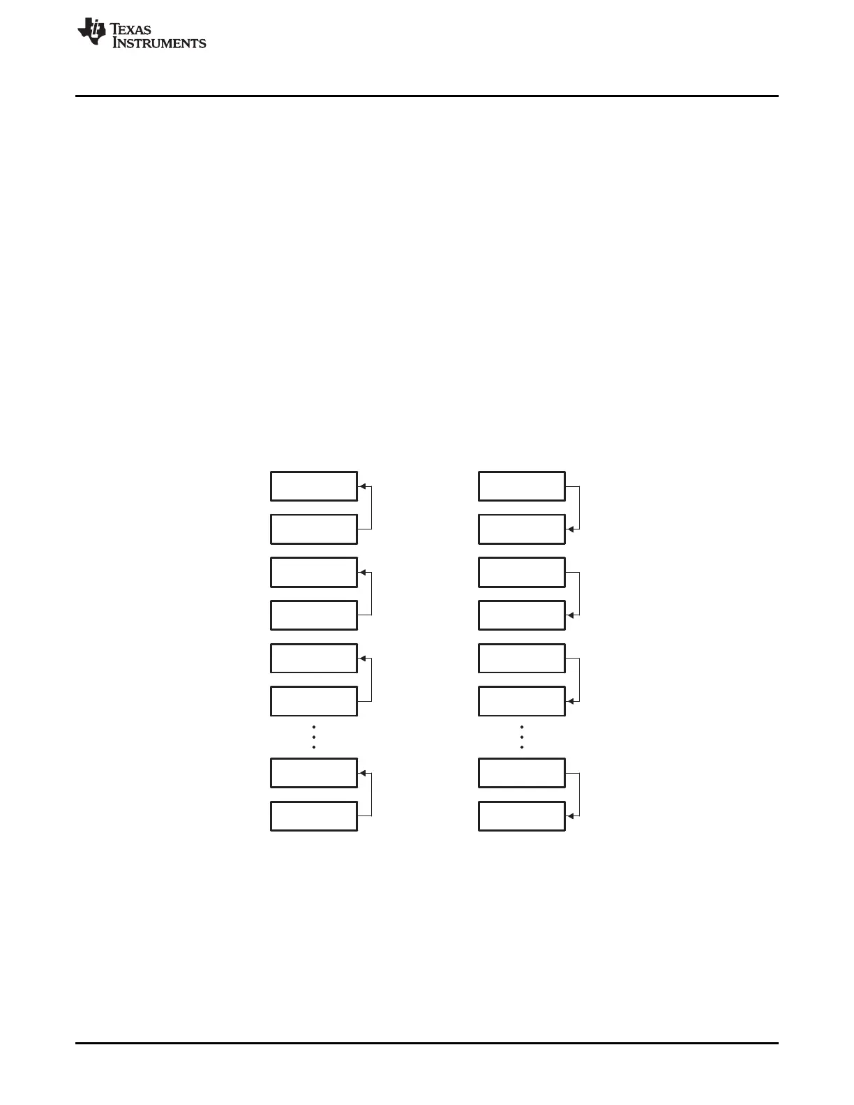
Figure 22-33 shows the basic logical connection of the serializers in loopback mode. Two types of
loopback connections are possible, selected by the ORD bit in the digital loopback control register
(DLBCTL) as follows:
• ORD = 0: Outputs of odd serializers are connected to inputs of even serializers. If this mode is
selected, you should configure odd serializers to be transmitters and even serializers to be receivers.
• ORD = 1: Outputs of even serializers are connected to inputs of odd serializers. If this mode is
selected, you should configure even serializers to be transmitters and odd serializers to be receivers.
Data can be externally visible at the I/O pin of the transmit serializer if the pin is configured as a McASP
output pin by setting the corresponding PFUNC bit to 0 and PDIR bit to 1.
In loopback mode, the transmit clock and frame sync are used by both the transmit and receive sections
of the McASP. The transmit and receive sections operate synchronously. This is achieved by setting the
MODE bit of the DLBCTL register to 01b and the ASYNC bit of the ACLKXCTL register to 0.
Figure 22-33. Serializers in Loopback Mode
3815
SPRUH73H–October 2011–Revised April 2013 Multichannel Audio Serial Port (McASP)
Submit Documentation Feedback
Copyright © 2011–2013, Texas Instruments Incorporated

 Loading...


