www.ti.com
I2C Registers
21.4.1.25 I2C_SYSTEST Register (offset = BCh) [reset = 0h]
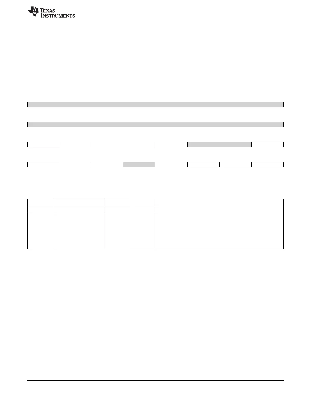
I2C_SYSTEST is shown in Figure 21-40 and described in Table 21-33.
CAUTION: Never enable this register for normal I2C operation This register is used to facilitate system-
level tests by overriding some of the standard functional features of the peripheral. It allows testing of SCL
counters, controlling the signals that connect to I/O pins, or creating digital loop-back for self-test when the
module is configured in system test (SYSTEST) mode. It also provides stop/non-stop functionality in the
debug mode.
Figure 21-40. I2C_SYSTEST Register
31 30 29 28 27 26 25 24
Reserved
R-0h
23 22 21 20 19 18 17 16
Reserved
R-0h
15 14 13 12 11 10 9 8
ST_EN FREE TMODE SSB Reserved SCL_I_FUNC
R/W-0h R/W-0h R/W-0h R/W-0h R-0h R-0h
7 6 5 4 3 2 1 0
SCL_O_FUNC SDA_I_FUNC SDA_O_FUNC Reserved SCL_I SCL_O SDA_I SDA_O
R-0h R-0h R-0h R-0h R-0h R-0h R-0h R-0h
LEGEND: R/W = Read/Write; R = Read only; W1toCl = Write 1 to clear bit; -n = value after reset
Table 21-33. I2C_SYSTEST Register Field Descriptions
Bit Field Type Reset Description
31-16 Reserved R 0h
15 ST_EN R/W 0h System test enable.
This bit must be set to 1 to permit other system test registers bits to
be set.
Value after reset is low.
0x0 = Normal mode. All others bits in register are read only.
0x1 = System test enabled. Permit other system test registers bits to
be set.
3757
SPRUH73H–October 2011–Revised April 2013 I2C
Submit Documentation Feedback
Copyright © 2011–2013, Texas Instruments Incorporated

 Loading...


