Multimedia Card Registers
www.ti.com
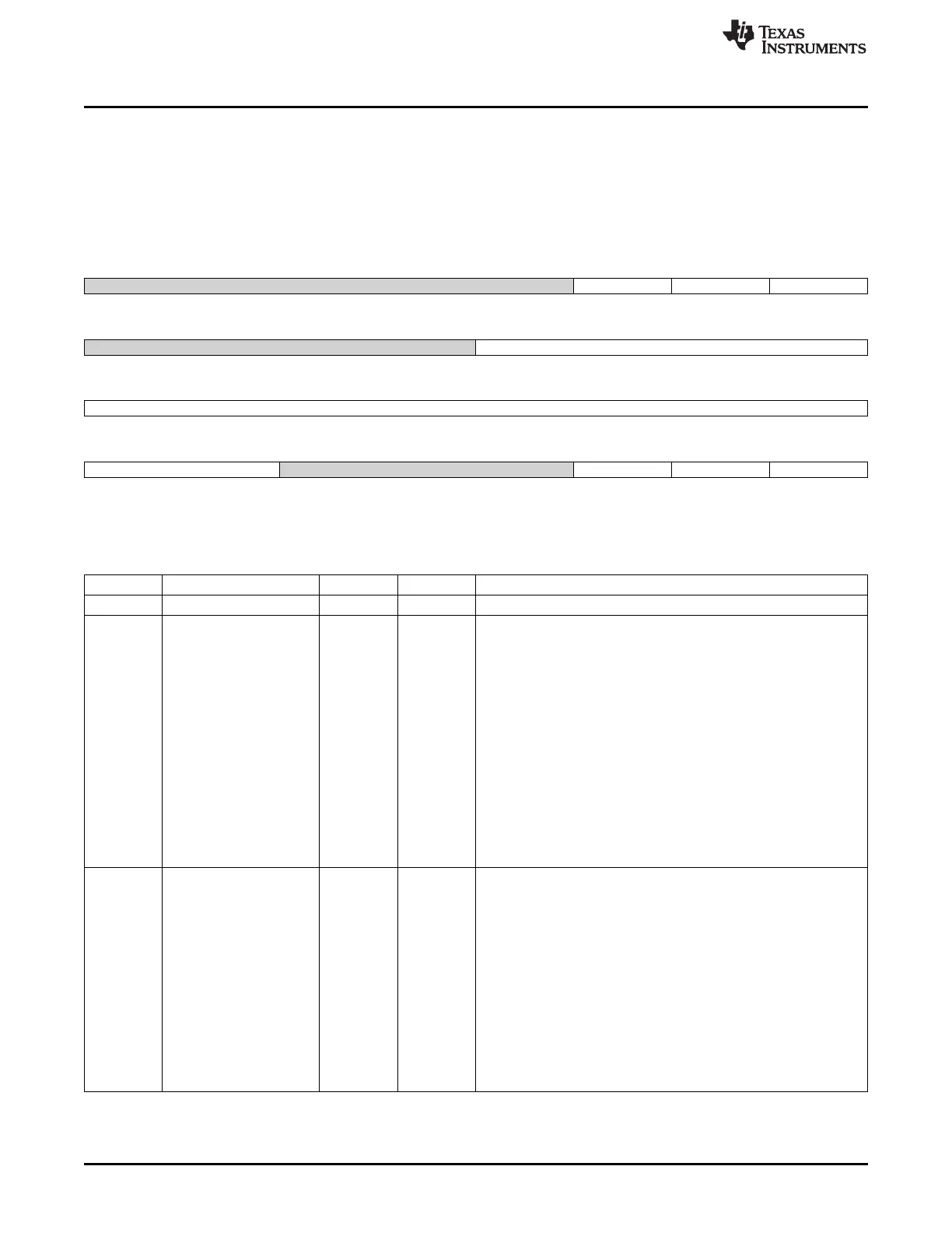
18.5.1.18 SD_SYSCTL Register (offset = 22Ch) [reset = 0h]
SD_SYSCTL is shown in Figure 18-54 and described in Table 18-37.
This register defines the system controls to set software resets, clock frequency management and data
timeout. SD_SYSCTL[31:24] = Software resets. SD_SYSCTL[23:16] = Timeout control. SD_SYSCTL[15:0]
= Clock control.
Figure 18-54. SD_SYSCTL Register
31 30 29 28 27 26 25 24
Reserved SRD SRC SRA
R-0h R/W-0h R/W-0h R/W-0h
23 22 21 20 19 18 17 16
Reserved DTO
R-0h R/W-0h
15 14 13 12 11 10 9 8
CLKD
R/W-0h
7 6 5 4 3 2 1 0
CLKD Reserved CEN ICS ICE
R/W-0h R-0h R/W-0h R-0h R/W-0h
LEGEND: R/W = Read/Write; R = Read only; W1toCl = Write 1 to clear bit; -n = value after reset
Table 18-37. SD_SYSCTL Register Field Descriptions
Bit Field Type Reset Description
31-27 Reserved R 0h
26 SRD R/W 0h Software reset for mmc_dat line.
This bit is set to 1 for reset and released to 0 when completed.
Due to additional implementation logic, the reset does not
immediately start when asserted.
The proper procedure is: (a) Set to 1 to start reset, (b) Poll for 1 to
identify start of reset, and (c) Poll for 0 to identify reset is complete.
mmc_dat finite state machine in both clock domain are also reset.
These registers are cleared by the SD_SYSCTL[26] SRD bit:
SD_DATA.
SD_PSTATEBRE, BWE, RTA, WTA, DLA and DATI.
SD_HCTLSBGR and CR.
SD_STATBRR, BWR, BGE and TC Interconnect and MMC buffer
data management is reinitialized.
Note: If a soft reset is issued when an interrupt is asserted, data may
be lost.
0x0 = Reset completed
0x1 = Software reset for mmc_dat line
25 SRC R/W 0h Software reset for mmc_cmd line.
This bit is set to 1 for reset and released to 0 when completed.
Due to additional implementation logic, the reset does not
immediately start when asserted.
The proper procedure is: (a) Set to 1 to start reset, (b) Poll for 1 to
identify start of reset, and (c) Poll for 0 to identify reset is complete.
mmc_cmd finite state machine in both clock domain are also reset.
These registers are cleared by the SD_SYSCTL[25] SRC bit:
SD_PSTATECMDI.
SD_STATCC Interconnect and MMC command status management
is reinitialized.
Note: If a soft reset is issued when an interrupt is asserted, data may
be lost.
0x0 = Reset completed
0x1 = Software reset for mmc_cmd line
3422
Multimedia Card (MMC) SPRUH73H–October 2011–Revised April 2013
Submit Documentation Feedback
Copyright © 2011–2013, Texas Instruments Incorporated

 Loading...


