0 1 2 3 4 5 6 7 8 9 10 11 12 13 14 15
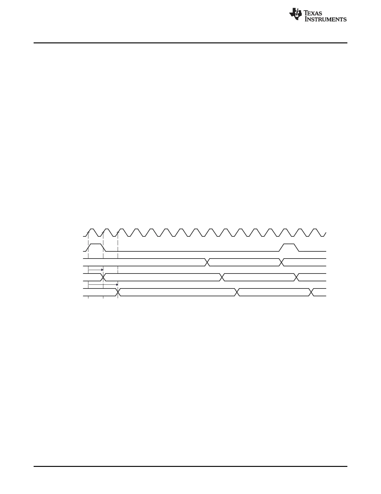
CLK
Frame
sync
Frame sync:
(0 bit delay)
Frame sync:
(1 bit delay)
Frame sync:
(2 bit delay)
Slot 0 Slot 1
Slot 0 Slot 1
Slot 0 Slot 1
Functional Description
www.ti.com
22.3.8 Transfer Modes
22.3.8.1 Burst Transfer Mode
The McASP supports a burst transfer mode, which is useful for nonaudio data such as passing control
information between two processors. Burst transfer mode uses a synchronous serial format similar to the
TDM mode. The frame sync generation is not periodic or time-driven as in TDM mode, but data driven,
and the frame sync is generated for each data word transferred.
When operating in burst frame sync mode (Figure 22-20), as specified for transmit (XMOD = 0 in
AFSXCTL) and receive (RMOD = 0 in AFSRCTL), one slot is shifted for each active edge of the frame
sync signal that is recognized. Additional clocks after the slot and before the next frame sync edge are
ignored.
In burst frame sync mode, the frame sync delay may be specified as 0, 1, or 2 serial clock cycles. This is
the delay between the frame sync active edge and the start of the slot. The frame sync signal lasts for a
single bit clock duration (FRWID = 0 in AFSRCTL, FXWID = 0 in AFSXCTL).
For transmit, when generating the transmit frame sync internally, the frame sync begins when the previous
transmission has completed and when all the XBUF[n] (for every serializer set to operate as a transmitter)
has been updated with new data.
For receive, when generating the receive frame sync internally, frame sync begins when the previous
transmission has completed and when all the RBUF[n] (for every serializer set to operate as a receiver)
has been read.
Figure 22-20. Burst Frame Sync Mode
The control registers must be configured as follows for the burst transfer mode. The burst mode specific
bit fields are in bold face:
• PFUNC: The clock, frame, data pins must be configured for McASP function.
• PDIR: The clock, frame, data pins must be configured to the direction desired.
• PDOUT, PDIN, PDSET, PDCLR: Not applicable. Leave at default.
• GBLCTL: Follow the initialization sequence in Section 22.3.12.2 to configure this register.
• AMUTE: Not applicable. Leave at default.
• DLBCTL: If loopback mode is desired, configure this register according to Section 22.3.10.5, otherwise
leave this register at default.
• DITCTL: DITEN must be left at default 0 to select non-DIT mode. Leave the register at default.
• RMASK/XMASK: Mask desired bits according to Section 22.3.9.2 and Section 22.3.10.3.
• RFMT/XFMT: Program all fields according to data format desired. See Section 22.3.10.3.
• AFSRCTL/AFSXCTL: Clear RMOD/XMOD bits to 0 to indicate burst mode. Clear FRWID/FXWID bits
to 0 for single bit frame sync duration. Configure other fields as desired.
• ACLKRCTL/ACLKXCTL: Program all fields according to bit clock desired. See Section 22.3.5.
• AHCLKRCTL/AHCLKXCTL: Program all fields according to high-frequency clock desired. See
Section 22.3.5.
3788
Multichannel Audio Serial Port (McASP) SPRUH73H–October 2011–Revised April 2013
Submit Documentation Feedback
Copyright © 2011–2013, Texas Instruments Incorporated

 Loading...


