www.ti.com
Functional Description
16.3.8.1.2 Bulk Transfer: Peripheral Mode
Bulk transactions are handled by endpoints other than endpoint 0. It is used to handle non-periodic, large
bursty communication typically used for a transfer that use any available bandwidth and can also be
delayed until bandwidth is available.
16.3.8.1.2.1 Bulk IN Transactions: Peripheral Mode
A Bulk IN transaction is used to transfer non-periodic data from the USB peripheral device to the host.
The following optional features are available for use with a Tx endpoint used in peripheral mode for Bulk
IN transactions:
• Double packet buffering: When enabled, up to two packets can be stored in the FIFO awaiting
transmission to the host. Double packet buffering is enabled by setting the DPB bit of TXFIFOSZ
register (bit 4).
• DMA: If DMA is enabled for the endpoint, a DMA request will be generated whenever the endpoint is
able to accept another packet in its FIFO. This feature allows the DMA controller to load packets into
the FIFO without processor intervention
16.3.8.1.2.1.1 Bulk IN Transaction Setup: Peripheral Mode
In configuring a TX endpoint for bulk transactions, the TXMAXP register must be written with the
maximum packet size (in bytes) for the endpoint. This value should be the same as the wMaxPacketSize
field of the Standard Endpoint Descriptor for the endpoint and the PERI_TXCSR register (DMAEN and
DMAMODE bit fields should be set when using DMA. Table 16-4 displays the PERI_TXCSR setting when
used for Bulk transfer.
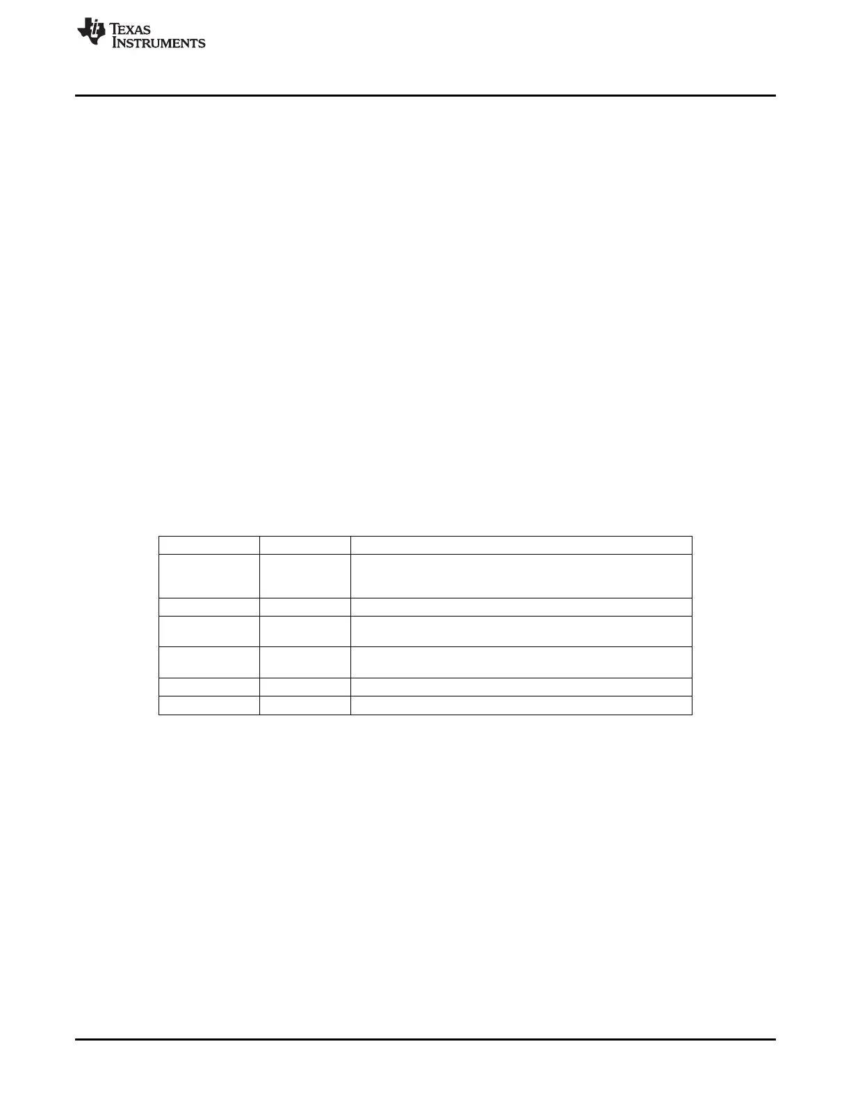
Table 16-4. PERI_TXCSR Register Bit Configuration for Bulk IN Transactions
Bit Field Bit Name Description
Bit 15 AUTOSET Cleared to 0 if using DMA. For CPU Mode use, if AUTOSET bit is
set, the TXPKTRDY bit will be automatically set when data of the
maximum packet size is loaded into the FIFO.
Bit 14 ISO Cleared to 0 for bulk mode operation.
Bit 13 MODE Set to 1 to make sure the FIFO is enabled (only necessary if the
FIFO is shared with an RX endpoint)
Bit 12 DMAEN Set to 1 to enable DMA usage; not needed if CPU is being used to
service the Tx Endpoint
Bit 11 FRCDATATOG Cleared to 0 to allow normal data toggle operations.
Bit 10 DMAMODE Set to 1 when DMA is used to service Tx FIFO.
When the endpoint is first configured (following a SET_CONFIGURATION or SET_INTERFACE command
on Endpoint 0), the lower byte of PERI_TXCSR should be written to set the CLRDATATOG bit (bit 6). This
will ensure that the data toggle (which is handled automatically by the controller) starts in the correct state.
Also if there are any data packets in the FIFO, indicated by the FIFONOTEMPTY bit (bit 1 of
PERI_TXCSR) being set, they should be flushed by setting the FLUSHFIFO bit (bit 3 of PERI_TXCSR).
NOTE: It may be necessary to set this bit twice in succession if double buffering is enabled.
1711
SPRUH73H–October 2011–Revised April 2013 Universal Serial Bus (USB)
Submit Documentation Feedback
Copyright © 2011–2013, Texas Instruments Incorporated

 Loading...


