L4 Peripheral
Interconnect
EDMA
PRCM
DCAN
intr0_intr_pend
DCANx_TX
intr1_intr_pend
dcan_io_clk
CAN_CLK
uerr_intr_pend
DCAN Pads
CLK_M_OSC
DCANx_RX
mmistart
mmidone
if3_dreq
MPU Subsystem,
PRU-ICSS (DCAN0 only)
CAN
Transceiver
TXD
RXD
CANH
CANL
Control
Module
if1_dreq
if2_dreq
www.ti.com
Integration
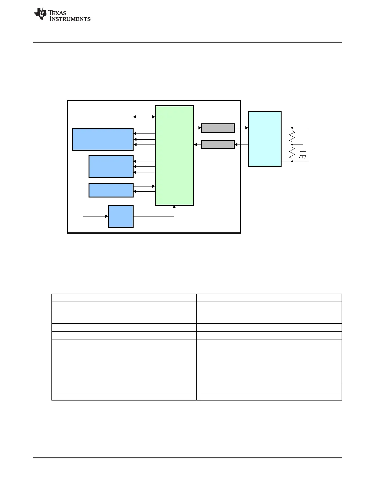
23.2 Integration
The Controller Area Network is a serial communications protocol which efficiently supports distributed
realtime control with a high level of security. The DCAN module supports bitrates up to 1 Mbit/s and is
compliant to the CAN 2.0B protocol specification. The core IP within DCAN is provided by Bosch.
This device includes two instantiations of the DCAN controller: DCAN0 and DCAN1. Figure 23-1 shows
the DCAN module integration.
Figure 23-1. DCAN Integration
23.2.1 DCAN Connectivity Attributes
The general connectivity attributes for the DCAN module are shown in Table 23-1.
Table 23-1. DCAN Connectivity Attributes
Attributes Type
Power Domain Peripheral Domain
Clock Domain PD_PER_L4LS_GCLK (OCP)
PD_PER_CAN_CLK (Func)
Reset Signals PER_DOM_RST_N
Idle/Wakeup Signals Smart Idle
Interrupt Requests
3 Interrupts per instance
Intr0 (DCANx_INT0) – Error, Status, Msg Object interrupt
Intr1 (DCANx_INT1) – Msg Object interrupt
Uerr (DCANx_PARITY) – Parity error interrupt
All DCAN0 interrupts to MPU Subsystem and PRU-ICSS
All DCAN1 interrupts to only MPU Subsystem
DMA Requests 3 DMA requests per instance to EDMA (CAN_IFxDMA)
Physical Address L4 Peripheral slave port
3883
SPRUH73H–October 2011–Revised April 2013 Controller Area Network (CAN)
Submit Documentation Feedback
Copyright © 2011–2013, Texas Instruments Incorporated

 Loading...


