www.ti.com
Functional Description
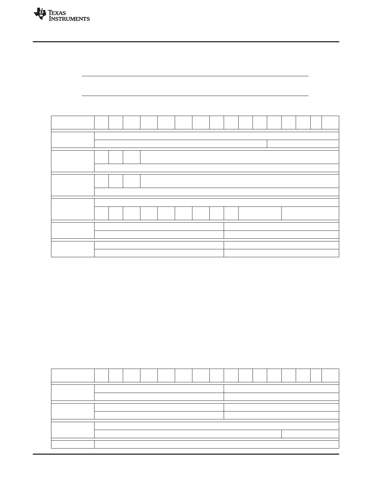
23.3.18.3 Message RAM Representation in Debug/Suspend Mode
In debug/suspend mode, the message RAM will be memory mapped. This allows the external debug unit
to access the message RAM.
NOTE: During debug/suspend mode, the message RAM cannot be accessed via the IFx register
sets.
Table 23-11. Message RAM Representation in Debug/Suspend Mode
31/ 30/ 29/ 29/ 27/ 26/ 25/ 24/ 23/ 22/ 21/ 20/ 19/ 18/ 17/ 16/
Bit #
15 14 13 12 11 10 9 8 7 6 5 4 3 2 1 0
Reserved
MsgAddr + 0x00 Reserved Parity[4:0]
MXt
MDir Rsvd Msk[28:16]
d
MsgAddr + 0x04 Msk[15:0]
Rsv
Xtd Dir ID[28:16]
d
MsgAddr + 0x08 ID[15:0]
Reserved
Rsv Msg UMas RmtE Rsv
MsgAddr + 0x0C Rsvd TxIE RxTE EOB Reserved DLC[3:0]
d Lst k n d
Data 3 Data 2
MsgAddr + 0x10 Data 1 Data 0
Data 7 Data 6
MsgAddr + 0x14 Data 5 Data 4
23.3.18.4 Message RAM Representation in Direct Access Mode
When the RDA bit in the test register is set while the DCAN module is in test mode (test bit in the CAN
control register is set), the CPU has direct access to the message RAM. Due to the 32-bit bus structure,
the RAM is split into word lines to support this feature. The CPU has access to one word line at a time
only.
In RAM direct access mode, the RAM is represented by a continuous memory space within the address
frame of the DCAN module, starting at the message RAM base address.
Note: During direct access mode, the message RAM cannot be accessed via the IFx register sets.
Any read or write to the RAM addresses for RamDirectAccess during normal operation mode (TestMode
bit or RDA bit not set) will be ignored.
Table 23-12. Message RAM Representation in RAM Direct Access Mode
31/ 30/ 29/ 29/ 27/ 26/ 25/ 24/ 23/ 22/ 21/ 20/ 19/ 18/ 17/ 16/
Bit #
15 14 13 12 11 10 9 8 7 6 5 4 3 2 1 0
Data 4 Data 5
MsgAddr + 0x00 Data 6 Data 7
Data 0 Data 1
MsgAddr + 0x04 Data 2 Data 3
ID[27:12]
MsgAddr + 0x08 ID[11:0] DLC[3:0]
Msk[28:13]
3921
SPRUH73H–October 2011–Revised April 2013 Controller Area Network (CAN)
Submit Documentation Feedback
Copyright © 2011–2013, Texas Instruments Incorporated

 Loading...


