www.ti.com
LCD Registers
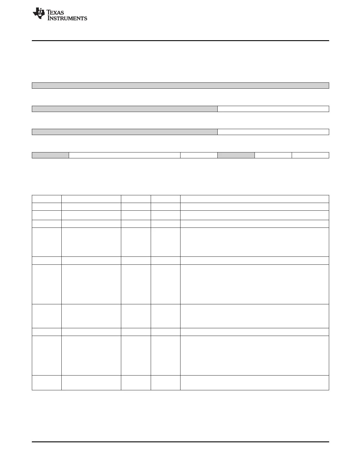
13.5.16 LCDDMA_CTRL Register (offset = 40h) [reset = 0h]
LCDDMA_CTRL is shown in Figure 13-34 and described in Table 13-29.
Figure 13-34. LCDDMA_CTRL Register
31 30 29 28 27 26 25 24
Reserved
R/W-0h
23 22 21 20 19 18 17 16
Reserved dma_master_prio
R/W-0h R/W-0h
15 14 13 12 11 10 9 8
Reserved th_fifo_ready
R/W-0h R/W-0h
7 6 5 4 3 2 1 0
Reserved burst_size byte_swap Reserved bigendian frame_mode
R/W-0h R/W-0h R/W-0h R-0h R/W-0h R/W-0h
LEGEND: R/W = Read/Write; R = Read only; W1toCl = Write 1 to clear bit; -n = value after reset
Table 13-29. LCDDMA_CTRL Register Field Descriptions
Bit Field Type Reset Description
31-19 Reserved R/W 0h
18-16 dma_master_prio R/W 0h
Priority for the L3 OCP Master Bus
15-11 Reserved R/W 0h
10-8 th_fifo_ready R/W 0h DMA FIFO threshold
The DMA FIFO becomes ready when the number of words specified
by this register from the frame buffer have been loaded
000 = 8 001 = 16 010 = 32 011 = 64 100 = 128 101 = 256 110 = 512
111 = reserved
7 Reserved R/W 0h
6-4 burst_size R/W 0h Burst Size setting for DMA transfers (all DMA transfers are 32 bits
wide): 000 = burst size of 1 001 = burst size of 2 010 = burst size of
4 011 = burst size of 8 100 = burst size of 16 101 = N/A 110 = N/A
111 = N/A burst_size cannot be changed once the DMA is enabled
in LIDD or Raster modes
In this case, the DMA must be disabled and the Done Interrupt must
occur before the value in this register can be changed
3 byte_swap R/W 0h This bit controls the bytelane ordering of the data on the output of
the DMA module
It works in conjunction with the big-endian bit
See the big-endian description for configuration guidelines
2 Reserved R 0h
1 bigendian R/W 0h Big Endian Enable
Use this bit when the processor is operating in Big Endian mode
AND writes to the frame buffer(s) are less than 32 bits wide
Only in this scenario do we need to change the byte alignment for
data coming into the FIFO from the frame buffer(s)
0 = Big Endian data reordering disabled 1 = Big Endian data
reordering enabled
0 frame_mode R/W 0h
Frame Mode 0 = one frame buffer (FB0 only) used 1 = two frame
buffers used DMA ping-pongs between FB0 and FB1 in this mode
1147
SPRUH73H–October 2011–Revised April 2013 LCD Controller
Submit Documentation Feedback
Copyright © 2011–2013, Texas Instruments Incorporated

 Loading...


