Prescaler
(1:128 ratio)
Counter
(32−bit)
WDTi_FCLK
RESET
IRQ
Registers
L4 interface
Watchdog timer
Interrupt
generation
www.ti.com
WATCHDOG
20.4.3 Functional Description
20.4.3.1 Power Management
There are two clock domains in the watchdog timers:
• Functional clock domain: WDTi_FCLK is a 32 kHz watchdog timer functional clock. It is used to clock
the watchdog timer internal logic.
• Interface clock domain: WDTi_ICLK is a 125 MHz watchdog timer interface clock. It is used to
synchronize the watchdog timer L4 port to the L4 interconnect. All accesses from the interconnect are
synchronous to WDTi_ICLK.
In this device, the clocks to the watchdog timers are always On. The clocks cannot be turned off, if the
watchdog timers is not being used.
20.4.3.2 Interrupts
Table 20-101 list the event flags, and their masks, that cause module interrupts.
Table 20-101. Watchdog Timer Events
Event Flag Event Mask Mapping Comments
WDT_WIRQSTAT[0] EVENT_OVF WDT_WIRQENSET/WDT_WIRQENCLR[0] WDTINT Watchdog timer overflow
OVF_IT_ENA
WDT_WIRQSTAT[1] EVENT_DLY WDT_WIRQENSET/WDT_WIRQENCLR[1] WDTINT Watchdog delay value
DLY_IT_ENA reached
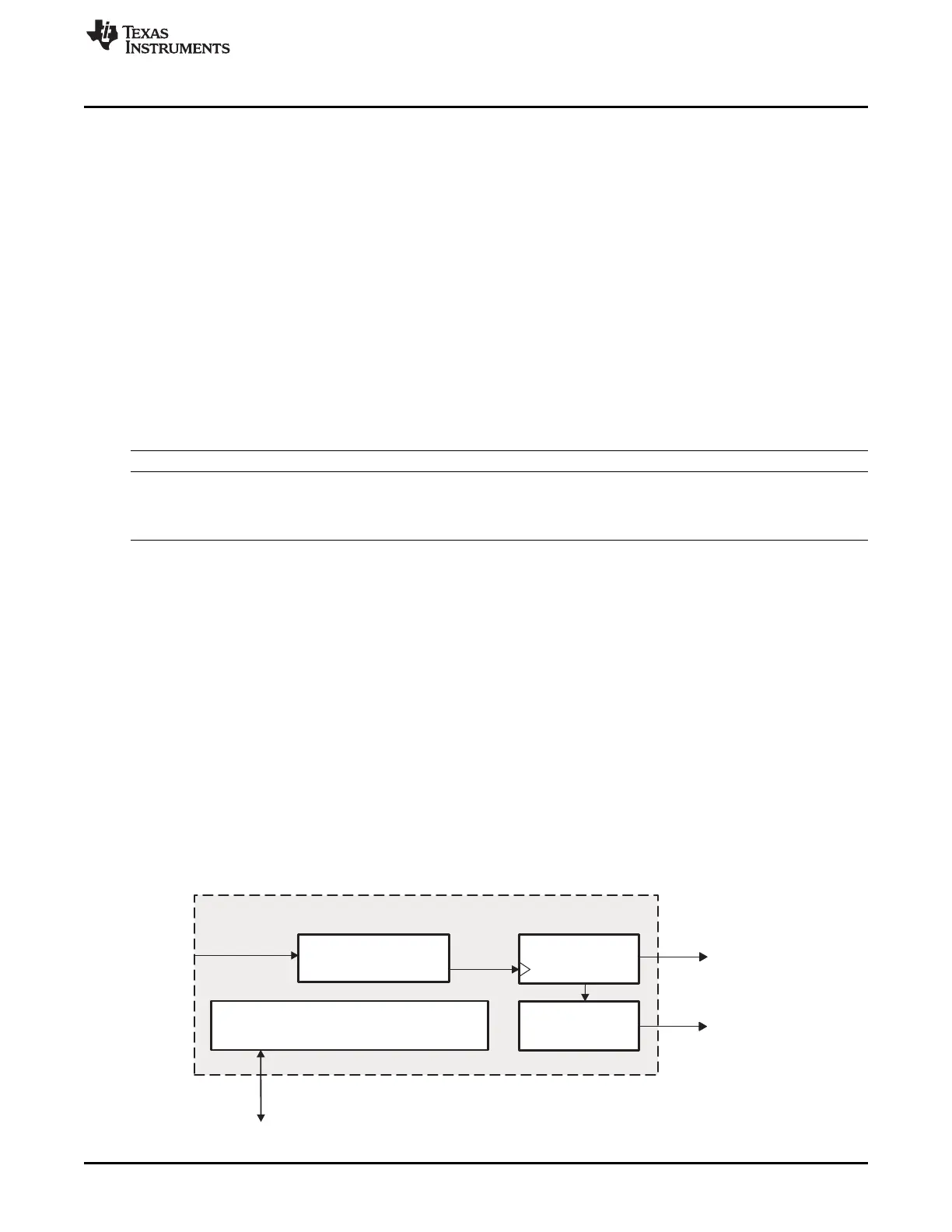
20.4.3.3 General Watchdog Timer Operation
The watchdog timers are based on an upward 32-bit counter coupled with a prescaler. The counter
overflow is signaled through two independent signals: a simple reset signal and an interrupt signal, both
active low. Figure 20-97 is a functional block diagram of the watchdog timer.
The interrupt generation mechanism is controlled through the WDT_WIRQENSET/WDT_WIRQENCLR
and WDT_WIRQSTAT registers.
The prescaler ratio can be set from 1 to 128 by accessing the WDT_WCLR[4:2] PTV bit field and the
WDT_WCLR[5] PRE bit of the watchdog control register (WDT_WCLR).
The current timer value can be accessed on-the-fly by reading the watchdog timer counter register
(WDT_WCRR), modified by accessing the watchdog timer load register (WDT_WLDR) (no on-the-fly
update), or reloaded by following a specific reload sequence on the watchdog timer trigger register
(WDT_WTGR). A start/stop sequence applied to the watchdog timer start/stop register (WDT_WSPR) can
start and stop the watchdog timers.
Figure 20-97. 32-Bit Watchdog Timer Functional Block Diagram
3673
SPRUH73H–October 2011–Revised April 2013 Timers
Submit Documentation Feedback
Copyright © 2011–2013, Texas Instruments Incorporated

 Loading...


