RTC_SS
www.ti.com
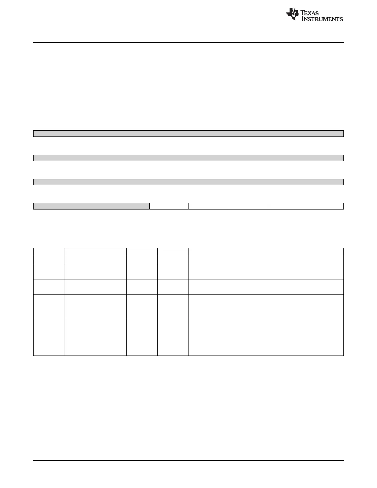
20.3.5.16 RTC_INTERRUPTS_REG Register (offset = 48h) [reset = 0h]
RTC_INTERRUPTS_REG is shown in Figure 20-76 and described in Table 20-79.
The RTC_INTERRUPTS_REG is used to enable or disable the RTC from generating interrupts. The timer
interrupt and alarm interrupt can be controlled using this register. The ARM must respect the BUSY period
to prevent spurious interrupt. To set a period timer interrupt, the respective period value must be set in the
EVERY field. For example, to set a periodic timer interrupt for every hour, the EVERY field has to be set
to 2. Along with this the IT_TIMER bit also has to be set for the periodic interrupt to be generated.
IT_ALARM bit has to be set to generate an alarm interrupt.
Figure 20-76. RTC_INTERRUPTS_REG Register
31 30 29 28 27 26 25 24
Reserved
R-0h
23 22 21 20 19 18 17 16
Reserved
R-0h
15 14 13 12 11 10 9 8
Reserved
R-0h
7 6 5 4 3 2 1 0
Reserved IT_ALARM2 IT_ALARM IT_TIMER EVERY
R-0h R/W-0h R/W-0h R/W-0h R/W-0h
LEGEND: R/W = Read/Write; R = Read only; W1toCl = Write 1 to clear bit; -n = value after reset
Table 20-79. RTC_INTERRUPTS_REG Register Field Descriptions
Bit Field Type Reset Description
31-5 Reserved R 0h
4 IT_ALARM2 R/W 0h
Enable one interrupt when the alarm value is reached (TC ALARM2
registers) by the TC registers
3 IT_ALARM R/W 0h
Enable one interrupt when the alarm value is reached (TC ALARM
registers) by the TC registers
2 IT_TIMER R/W 0h
Enable periodic interrupt.
0x0 = Interrupt disabled
0x1 = Interrupt enabled
1-0 EVERY R/W 0h
Interrupt period.
0x0 = Every second
0x1 = Every minute
0x2 = Every hour
0x3 = Every day
3650
Timers SPRUH73H–October 2011–Revised April 2013
Submit Documentation Feedback
Copyright © 2011–2013, Texas Instruments Incorporated

 Loading...


