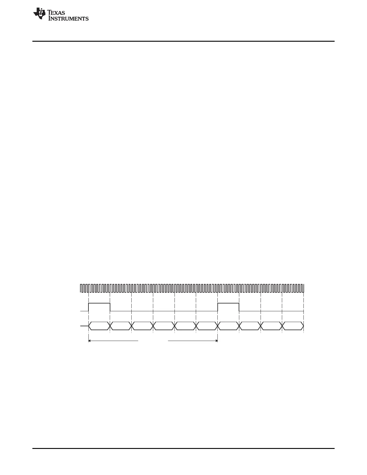
TDM frame
CLK
FS
(A)
AXR[n] Slot 0 Slot 1 Slot 3Slot 2 Slot 0Slot 5Slot 4 Slot 3Slot 2Slot 1
www.ti.com
Functional Description
22.3.3 Industry Standard Compliance Statement
The McASP supports the following industry standard interfaces.
22.3.3.1 TDM Format
The McASP transmitter and receiver support the multichannel, synchronous time-division-multiplexed
(TDM) format via the TDM transfer mode. Within this transfer mode, a wide variety of serial data formats
are supported, including formats compatible with devices using the Inter-Integrated Sound (I2S) protocol.
This section briefly discusses the TDM format and the I2S protocol.
22.3.3.1.1 TDM Format
The TDM format is typically used when communicating between integrated circuit devices on the same
printed circuit board or on another printed circuit board within the same piece of equipment. For example,
the TDM format is used to transfer data between the processor and one or more analog-to-digital
converter (ADC), digital-to-analog converter (DAC), or S/PDIF receiver (DIR) devices.
The TDM format consists of three components in a basic synchronous serial transfer: the clock, the data,
and the frame sync. In a TDM transfer, all data bits (AXRn) are synchronous to the serial clock (ACLKX or
ACLKR). The data bits are grouped into words and slots (as defined in Section 22.3.4). The "slots" are
also commonly referred to as "time slots" or "channels" in TDM terminology. A frame consists of multiple
slots (or channels). Each TDM frame is defined by the frame sync signal (AFSX or AFSR). Data transfer is
continuous and periodic, since the TDM format is most commonly used to communicate with data
converters that operate at a fixed sample rate.
There are no delays between slots. The last bit of slot N is followed immediately on the next serial clock
cycle with the first bit of slot N + 1, and the last bit of the last slot is followed immediately on the next serial
clock with the first bit of the first slot. However, the frame sync may be offset from the first bit of the first
slot with a 0, 1, or 2-cycle delay.
It is required that the transmitter and receiver in the system agree on the number of bits per slot, since the
determination of a slot boundary is not made by the frame sync signal (although the frame sync marks the
beginning of slot 0 and the beginning of a new frame).
Figure 22-8 shows the TDM format. Figure 22-9 shows the different bit delays from the frame sync.
Figure 22-8. TDM Format–6 Channel TDM Example
A FS duration of slot is shown. FS duration of single bit is also supported.
3777
SPRUH73H–October 2011–Revised April 2013 Multichannel Audio Serial Port (McASP)
Submit Documentation Feedback
Copyright © 2011–2013, Texas Instruments Incorporated

 Loading...


