McSPI Registers
www.ti.com
24.4.1.8 McSPI Channel (i) Configuration Register (MCSPI_CH(i)CONF)
The McSPI channel i configuration register (MCSPI_CH(i)CONF) is used to configure channel i. The
(MCSPI_CH(i)CONF) is shown in Figure 24-33 and described in Table 24-18.
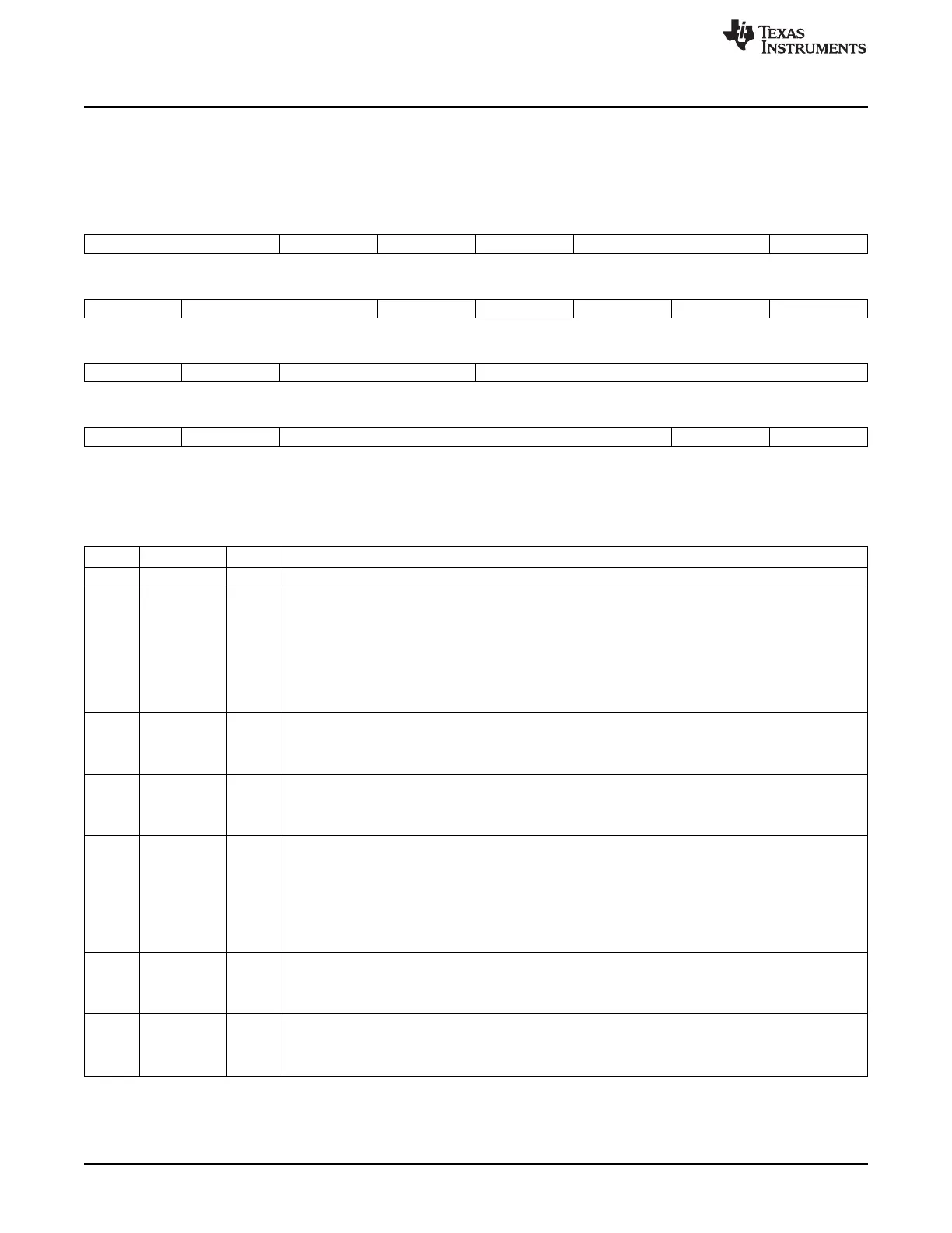
Figure 24-33. McSPI Channel (i ) Configuration Register (MCSPI_CH(i)CONF)
31 30 29 28 27 26 25 24
Reserved CLKG FFER FFEW TCS SBPOL
R/W-0 R/W-0 R/W-0 R/W-0 R/W-0 R/W-0
23 22 21 20 19 18 17 16
SBE SPIENSLV FORCE TURBO IS DPE1 DPE0
R/W-0 R/W-0 R/W-0 R/W-0 R/W-1 R/W-1 R/W-0
15 14 13 12 11 8
DMAR DMAW TRM WL
R/W-0 R/W-0 R/W-0 R/W-0
7 6 5 2 1 0
WL EPOL CLKD POL PHA
R/W-0 R/W-0 R/W-0 R/W-0 R/W-0
LEGEND: R/W = Read/Write; R = Read only; -n = value after reset
Table 24-18. McSPI Channel (i) Configuration Register (MCSPI_CH(i)CONF) Field Descriptions
Bit Field Value Description
31-30 Reserved 0 Read returns 0
29 CLKG Clock divider granularity. This register defines the granularity of channel clock divider: power of two or
one clock cycle granularity.
When this bit is set the register MCSPI_CHCTRL[EXTCLK] must be configured to reach a maximum of
4096 clock divider ratio. Then The clock divider ratio is a concatenation of MCSPI_CHCONF[CLKD] and
MCSPI_CHCTRL[EXTCLK] values.
0 Clock granularity of power of 2
1 1 clock cycle granularity
28 FFER FIFO enabled for receive. Only one channel can have this bit set.
0 The buffer is not used to receive data.
1 The buffer is used to receive data.
27 FFEW FIFO enabled for transmit. Only one channel can have this bit set.
0 The buffer is not used to transmit data.
1 The buffer is used to transmit data.
26-25 TCS Chip select time control. This 2-bits field defines the number of interface clock cycles between CS
toggling and first or last edge of SPI clock.
0 0.5 clock cycles
1h 1.5 clock cycles
2h 2.5 clock cycles
3h 3.5 clock cycles
24 SBPOL Start bit polarity.
0 Start bit polarity is held to 0 during SPI transfer.
1 Start bit polarity is held to 1 during SPI transfer.
23 SBE Start bit enable for SPI transfer.
0 Default SPI transfer length as specified by WL bit field.
1 Start bit D/CX added before SPI transfer. Polarity is defined by MCSPI_CH(i)CONF[SBPOL].
4046
Multichannel Serial Port Interface (McSPI) SPRUH73H–October 2011–Revised April 2013
Submit Documentation Feedback
Copyright © 2011–2013, Texas Instruments Incorporated

 Loading...


