McASP Registers
www.ti.com
22.4.1.11 Digital Loopback Control Register (DLBCTL)
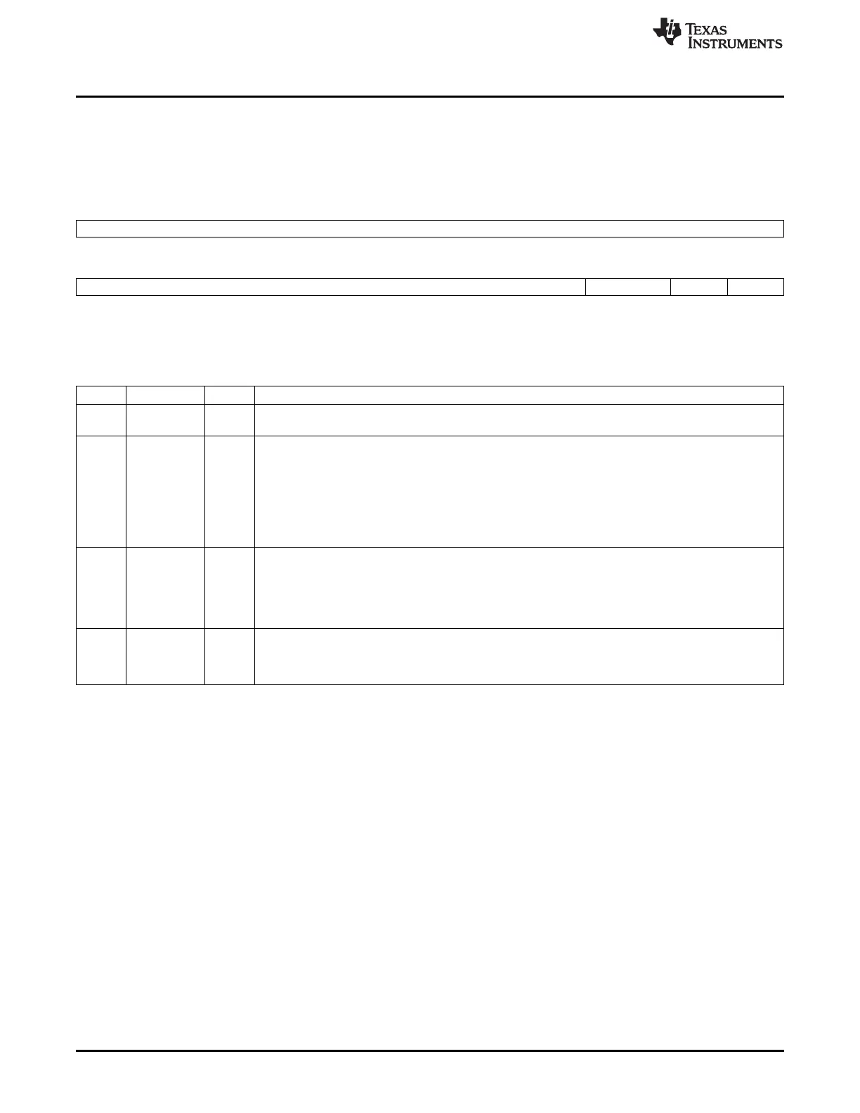
The digital loopback control register (DLBCTL) controls the internal loopback settings of the McASP in
TDM mode. The DLBCTL is shown in Figure 22-49 and described in Table 22-22.
Figure 22-49. Digital Loopback Control Register (DLBCTL)
31 16
Reserved
R-0
15 4 3 2 1 0
Reserved MODE ORD DLBEN
R-0 R/W-0 R/W-0 R/W-0
LEGEND: R/W = Read/Write; R = Read only; -n = value after reset
Table 22-22. Digital Loopback Control Register (DLBCTL) Field Descriptions
Bit Field Value Description
31-4 Reserved 0 Reserved. The reserved bit location always returns the default value. A value written to this field has no
effect. If writing to this field, always write the default value for future device compatibility.
3-2 MODE 0-3h Loopback generator mode bits. Applies only when loopback mode is enabled (DLBEN = 1).
0 Default and reserved on loopback mode (DLBEN = 1).
When in non-loopback mode (DLBEN = 0), MODE should be left at default (00).
When in loopback mode (DLBEN = 1), MODE = 00 is reserved and is not applicable.
1h Transmit clock and frame sync generators used by both transmit and receive sections. When in
loopback mode (DLBEN = 1), MODE must be 01.
2h-3h Reserved.
1 ORD Loopback order bit when loopback mode is enabled (DLBEN = 1).
0 Odd serializers N + 1 transmit to even serializers N that receive. The corresponding serializers must be
programmed properly.
1 Even serializers N transmit to odd serializers N + 1 that receive. The corresponding serializers must be
programmed properly.
0 DLBEN Loopback mode enable bit.
0 Loopback mode is disabled.
1 Loopback mode is enabled.
3846
Multichannel Audio Serial Port (McASP) SPRUH73H–October 2011–Revised April 2013
Submit Documentation Feedback
Copyright © 2011–2013, Texas Instruments Incorporated

 Loading...


