System
Core
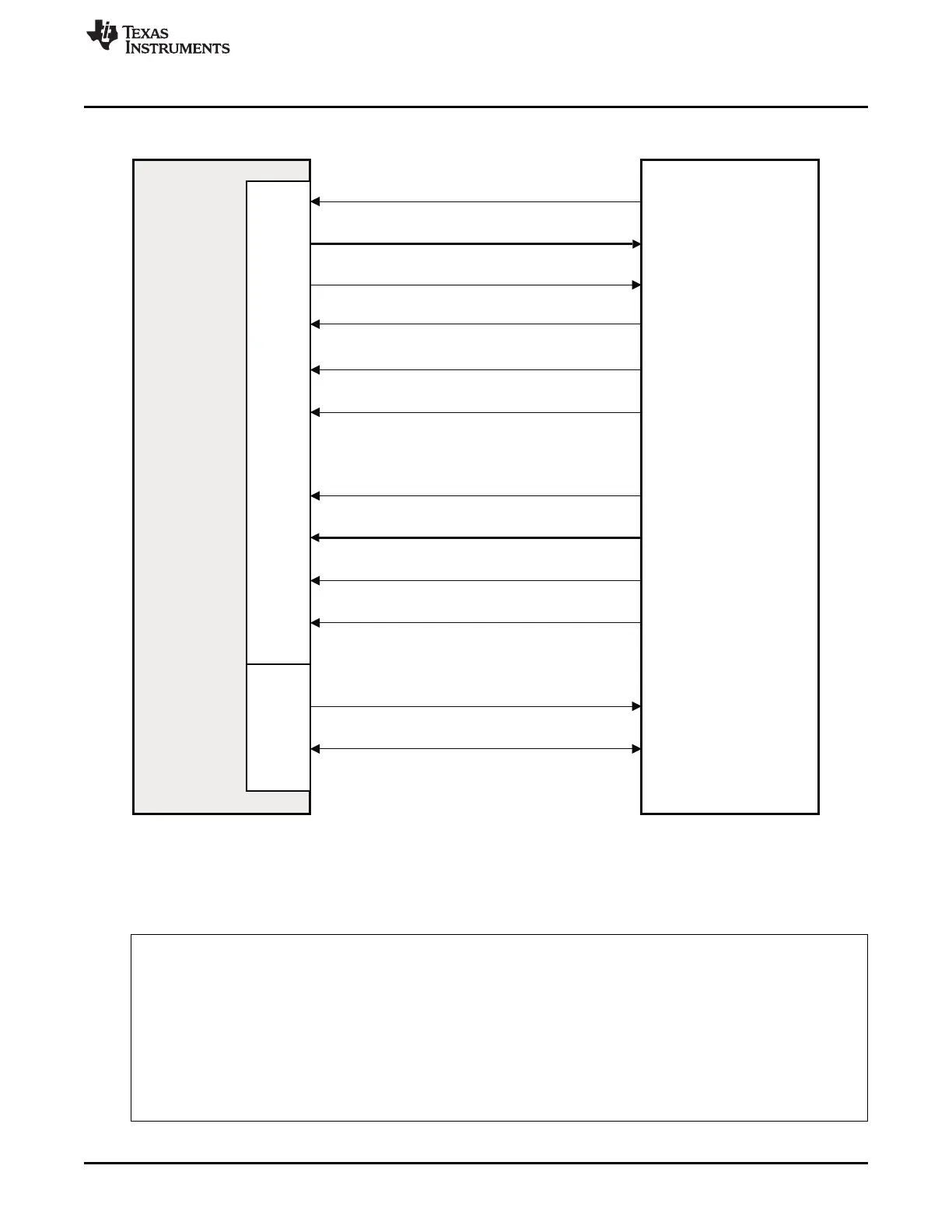
EMAC
MDIO
Physical
Layer
Device
(PHY)
GMII_TXCLK
GMII_TXD[7:0]
GMII_TXEN
GMII_COL
GMII_CRS
GMII_RXCLK
GMII_RXD[7:0]
GMII_RXDV
GMII_RXER
MDIO_CLK
MDIO_DATA
GMII_GMTCLK
www.ti.com
Integration
Figure 14-3. MII Interface Connections
The detailed description of the signals in GIG/MII Mode are explained in the following sections.
14.2.5.1 GMII Interface Signal Descriptions in GIG (1000Mbps) Mode
Table 14-5. GMII Interface Signal Descriptions in GIG (1000Mbps) Mode
Signal Type Description
The transmit clock is a continuous clock that provides the timing reference for
GMTCLK O transmit operations. The clock is generated by the CPSW and is 125 MHz at
1000 Mbps operation.
The transmit clock is a continuous free running clock and is generated by the
MtCLK I
PHY.
The transmit data pins are a collection of 8 data signals comprising 8 bits of data.
Mtxd O MTXD0 is the least-significant bit (LSB). The signals are synchronized by
GMTCLK and valid only when MTXEN is asserted.
The transmit enable signal indicates that the MTXD pins are generating 8bit data
Mtxen O
for use by the PHY. It is driven synchronously by GMTCLK.
1171
SPRUH73H–October 2011–Revised April 2013 Ethernet Subsystem
Submit Documentation Feedback
Copyright © 2011–2013, Texas Instruments Incorporated

 Loading...


