PRCM
LCD_CLK
0
1
2
CORE_CLKOUTM5
PER_CLKOUTM2
Display PLL
(ADPLLS)
CLKOUT
CLKDCOLDO
CLKOUTHIF
CLKINP
CLKINPULOW
ULOWPRIORITY
0
1
2
0
1
Master
Osc
(CLK_M_OSC)
ALT_CLK1
ALT_CLK2
TEST.CDR (via P1500)
ULOWCLKEN
0: CLKINP
1: CLKINPULOW
CORE_CLKOUTM6
PER_CLKOUTM2
CONTROL.PLL_CLKINPULOW_CTRL.DISP_
PLL_CLKINPULOW_SEL (Reset default = 0)
PRCM.CM_CLKSEL_DPLL_DISP.
DPLL_BYP_CLKSEL (Reset default = 0)
CLKOUTx2
PRCM.CLKSEL_LCDC_PIXEL_CLK
(Reset default = 0)
www.ti.com
Power, Reset, and Clock Management
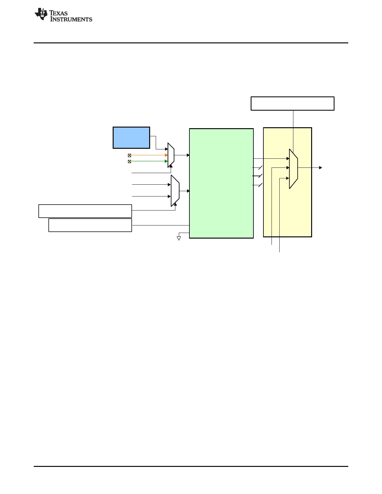
8.1.6.10 Display PLL Description
The Display PLL provides the pixel clock required for the LCD display and is independent from the other
peripheral and infrastructure clocks. The PLL is clocked from the Master Oscillator. The ADPLLS M2
divider determines the output clock frequency which is clock gated by the PRCM as shown in Figure 8-13.
Figure 8-13. Display PLL Structure
For example: say frequency for pixel clock 100 MHz, the ADPLLS is configured (PLL locked at 200 MHz
and M2 Divider =1) so as to expect CLKOUT = 100 MHz.
The ULOWCLKEN input from a programmable PRCM register selects whether CLKINP or CLKINPULOW
is the bypass clock source. This is a glitch free switch. When CLKINP is selected it is sourced through the
ADPLLS 1/(N2+1) divider. The PRCM register defaults to 0 on power-up to select the CLKINP source.
The CLKINPULOW input is sourced from the CORE_CLKOUTM6 from the Core PLL or PER_CLKOUTM2
from the Per PLL. This PLL output clock can be used as an alternate clock source in low power active use
cases for the pixel clock when the Display PLL is in bypass mode.
8.1.6.10.1 Configuring the Display PLL
The following steps detail how to configure the display PLL.
1. Switch PLL to bypass mode by setting CM_CLKMODE_DPLL_DISP.DPLL_EN to 0x4.
2. Wait for CM_IDLEST_DPLL_DISP.ST_MN_BYPASS = 1 to ensure PLL is in bypass
(CM_IDLEST_DPLL_DISP.ST_DPLL_CLK should also change to 0 to denote the PLL is unlocked).
3. Configure Multiply and Divide values by setting CM_CLKSEL_DPLL_DISP.DPLL_MULT and
DPLL_DIV to the desired values.
4. Configure M2 divider by setting CM_DIV_M2_DPLL_DISP.DPLL_CLKOUT_DIV to the desired value.
5. Switch over to lock mode by setting CM_CLKMODE_DPLL_DISP.DPLL_EN to 0x7.
6. Wait for CM_IDLEST_DPLL_DISP.ST_DPLL_CLK = 1 to ensure PLL is locked
(CM_IDLEST_DPLL_DISP.ST_MN_BYPASS should also change to 0 to denote the PLL is out of
bypass mode).
531
SPRUH73H–October 2011–Revised April 2013 Power, Reset, and Clock Management (PRCM)
Submit Documentation Feedback
Copyright © 2011–2013, Texas Instruments Incorporated

 Loading...


