Ethernet Subsystem Registers
www.ti.com
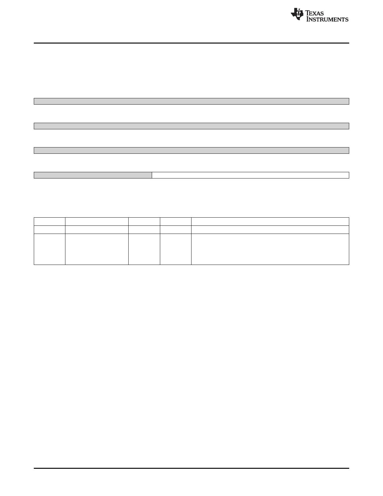
14.5.2.25 CPDMA_EOI_VECTOR Register (offset = 94h) [reset = 0h]
CPDMA_EOI_VECTOR is shown in Figure 14-53 and described in Table 14-64.
CPDMA_INT END OF INTERRUPT VECTOR
Figure 14-53. CPDMA_EOI_VECTOR Register
31 30 29 28 27 26 25 24
Reserved
R-0h
23 22 21 20 19 18 17 16
Reserved
R-0h
15 14 13 12 11 10 9 8
Reserved
R-0h
7 6 5 4 3 2 1 0
Reserved DMA_EOI_VECTOR
R-0h R/W-0h
LEGEND: R/W = Read/Write; R = Read only; W1toCl = Write 1 to clear bit; -n = value after reset
Table 14-64. CPDMA_EOI_VECTOR Register Field Descriptions
Bit Field Type Reset Description
31-5 Reserved R 0h
4-0 DMA_EOI_VECTOR R/W 0h DMA End of Interrupt Vector - The EOI_VECTOR(
4:0) pins reflect the value written to this location one CLK cycle after
a write to this location.
The EOI_WR signal is asserted for a single clock cycle after a
latency of two CLK cycles when a write is performed to this location.
1284
Ethernet Subsystem SPRUH73H–October 2011–Revised April 2013
Submit Documentation Feedback
Copyright © 2011–2013, Texas Instruments Incorporated

 Loading...


