Sync_Seg Prop_Seg Phase_Seg1 Phase_Seg2
Node B
Node A
Delay A_to_B Delay B_to_A
Prop_Seg >= Delay A_to_B + Delay B_to_A
Prop_Seg >= 2 • [max(node output delay+bus line delay + node input delay)]
Delay A_to_B >= node output delay(A) + bus line delay(AÆB) + node input delay(B)
Functional Description
www.ti.com
Table 23-7. Parameters of the CAN Bit Time
Parameter Range Remark
Sync_Seg 1 t
q
(fixed) Synchronization of bus input to CAN_CLK
Prop_Seg [1 … 8] t
q
Compensates for the physical delay times
Phase_Seg1 [1 … 8] t
q
May be lengthened temporarily by synchronization
Phase_Seg2 [1 … 8] t
q
May be shortened temporarily by synchronization
Synchronization Jump Width
[1 … 4] t
q
May not be longer than either Phase Buffer Segment
(SJW)
NOTE: For proper functionality of the CAN network, the physical delay times and the oscillator’s
tolerance range have to be considered.
23.3.16.1.1 Synchronization Segment
The synchronization segment (Sync_Seg) is the part of the bit time where edges of the CAN bus level are
expected to occur. If an edge occurs outside of Sync_Seg, its distance to the Sync_Seg is called the
phase error of this edge.
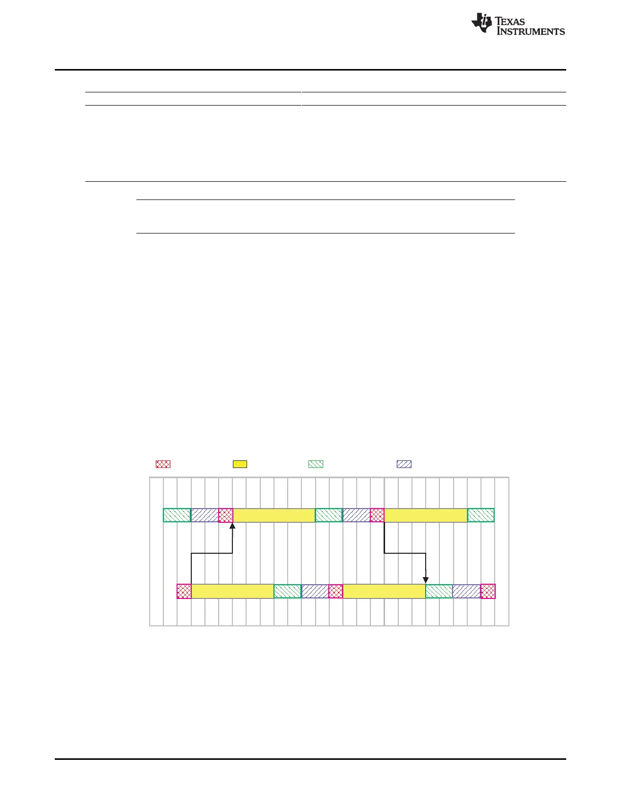
23.3.16.1.2 Propagation Time Segment
This part of the bit time is used to compensate physical delay times within the CAN network. These delay
times consist of the signal propagation time on the bus and the internal delay time of the CAN nodes.
Any CAN node synchronized to the bit stream on the CAN bus can be out of phase with the transmitter of
the bit stream, caused by the signal propagation time between the two nodes. The CAN protocol’s
nondestructive bitwise arbitration and the dominant acknowledge bit provided by receivers of CAN
messages require that a CAN node transmitting a bit stream must also be able to receive dominant bits
transmitted by other CAN nodes that are synchronized to that bit stream. The example in Figure 23-14
shows the phase shift and propagation times between two CAN nodes.
Figure 23-14. The Propagation Time Segment
3908
Controller Area Network (CAN) SPRUH73H–October 2011–Revised April 2013
Submit Documentation Feedback
Copyright © 2011–2013, Texas Instruments Incorporated

 Loading...


