www.ti.com
Power, Reset, and Clock Management
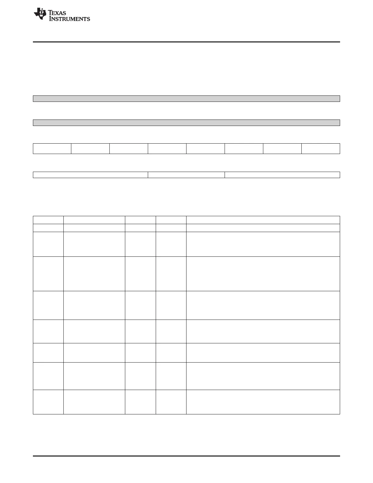
8.1.12.2.38 CM_CLKMODE_DPLL_DDR Register (offset = 94h) [reset = 4h]
CM_CLKMODE_DPLL_DDR is shown in Figure 8-121 and described in Table 8-129.
This register allows controlling the DPLL modes.
Figure 8-121. CM_CLKMODE_DPLL_DDR Register
31 30 29 28 27 26 25 24
Reserved
R-0h
23 22 21 20 19 18 17 16
Reserved
R-0h
15 14 13 12 11 10 9 8
DPLL_SSC_TYPE DPLL_SSC_DOWNS DPLL_SSC_ACK DPLL_SSC_EN DPLL_REGM4XEN DPLL_LPMODE_EN DPLL_RELOCK_RAM DPLL_DRIFTGUARD
PREAD P_EN _EN
R/W-0h R/W-0h R-0h R/W-0h R-0h R/W-0h R/W-0h R/W-0h
7 6 5 4 3 2 1 0
DPLL_RAMP_RATE DPLL_RAMP_LEVEL DPLL_EN
R/W-0h R/W-0h R/W-4h
LEGEND: R/W = Read/Write; R = Read only; W1toCl = Write 1 to clear bit; -n = value after reset
Table 8-129. CM_CLKMODE_DPLL_DDR Register Field Descriptions
Bit Field Type Reset Description
31-16 Reserved R 0h
15 DPLL_SSC_TYPE R/W 0h Select Triangular Spread Spectrum clocking.
Always write 0.
0 = Triangular Spread Spectrum Clocking is selected.
1 = Reserved.
14 DPLL_SSC_DOWNSPRE R/W 0h
Control if only low frequency spread is required
AD
0x0 = FULL_SPREAD : When SSC is enabled, clock frequency is
spread on both sides of the programmed frequency
0x1 = LOW_SPREAD : When SSC is enabled, clock frequency is
spread only on the lower side of the programmed frequency
13 DPLL_SSC_ACK R 0h
Acknowledgement from the DPLL regarding start and stop of Spread
Spectrum Clocking feature
0x0 = Disabled : SSC has been turned off on PLL o/ps
0x1 = Enabled : SSC has been turned on on PLL o/ps
12 DPLL_SSC_EN R/W 0h
Enable or disable Spread Spectrum Clocking
0x0 = Disabled : SSC disabled
0x1 = Enabled : SSC enabled
11 DPLL_REGM4XEN R 0h Enable the REGM4XEN mode of the DPLL.
Please check the DPLL documentation to check when this mode can
be enabled.
10 DPLL_LPMODE_EN R/W 0h Set the DPLL in Low Power mode.
Check the DPLL documentation to see when this can be enabled.
0x0 = DISABLED : Low power mode of the DPLL is disabled
0x1 = ENABLED : Low power mode of the DPLL is enabled
9 DPLL_RELOCK_RAMP_E R/W 0h If enabled, the clock ramping feature is used applied during the lock
N process, as well as the relock process.
If disabled, the clock ramping feature is used only during the first
lock.
655
SPRUH73H–October 2011–Revised April 2013 Power, Reset, and Clock Management (PRCM)
Submit Documentation Feedback
Copyright © 2011–2013, Texas Instruments Incorporated

 Loading...


