clk
cmd
CMD1
RESP
CMD2
RESP
CMD3
RESP
S
010
E
512 Bytes
+ CRC
S
512 Bytes
+ CRC
S
E
dat0
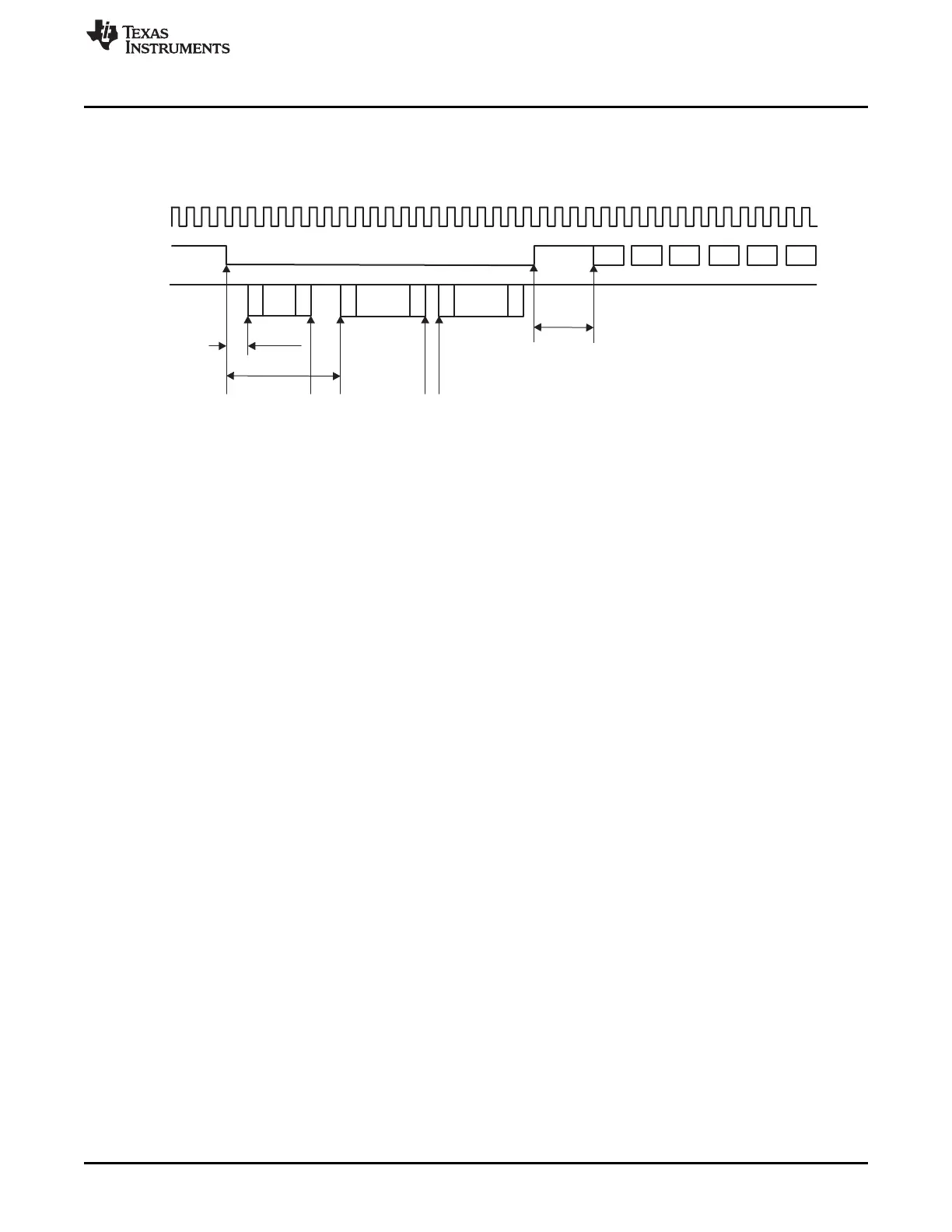
50ms max
1 sec. max
Min. 8 clocks + 48 clocks = 56 clocks required
from CMD signal high to next MMC command.
Boot Terminated
E
www.ti.com
Functional Description
18.3.13.2 Boot Mode With CMD Held Low
Figure 18-32 shows the timing diagram of a boot sequence with CMD line tied to 0.
Figure 18-32. Boot Mode With CMD Line Tied to 0
• Configure:
– MMCHS_CON[BOOT_CF0] and MMCHS_CON[BOOT_ACK] (if an acknowledge will be received)
to 0x1
– MMCHS_BLK with correct block length and number of block
– MMCHS_SYSCTL[DTO] for timeout
If transfer is done in DDR mode also set MMCHS_CON[DDR] to 1.
• Write in MMCHS_CMD register to start boot sequence with:
– DP set to '1'
– DDIR set to '1'
– MSBS set to '1'
– BCE set to '1'
This leads the controller to force CMD line to '0'.
• If the boot status is not received within the timing defined, the MMCHS_STAT[DTO] will be generated.
Otherwise the MMCHS_STAT[BSR] is arisen.
• After the transfer is complete, the controller will generate the MMCHS_STAT[TC], and then the system
must clear MMCHS_CON[BOOT_CF0] to 0x0 to release the CMD line and enable the card to exit from
boot state.
• If the system wants to abort the boot sequence it must clear MMCHS_CON[BOOT_CF0] to 0x0 during
transfer to enable the card to exit from boot state.
3381
SPRUH73H–October 2011–Revised April 2013 Multimedia Card (MMC)
Submit Documentation Feedback
Copyright © 2011–2013, Texas Instruments Incorporated

 Loading...


