System
DMA
System
Interrupt
System
Clock
Unit
Local
Host
SPI Interface
Reference Clock
*CLK: Functional Reference Clock
DMA_TX_REQ
WAKE_REQ
CLK*
McSPI
(Master/Slave)
SPICLK
SPIDAT[0]
SPIDAT[1]
SPIEN[3:0]
(Touch Screen,
LCD, Audio
Codec, etc.)
External SPI Compliant Devices
(Single Master or Slave)
ASIC
www.ti.com
Functional Description
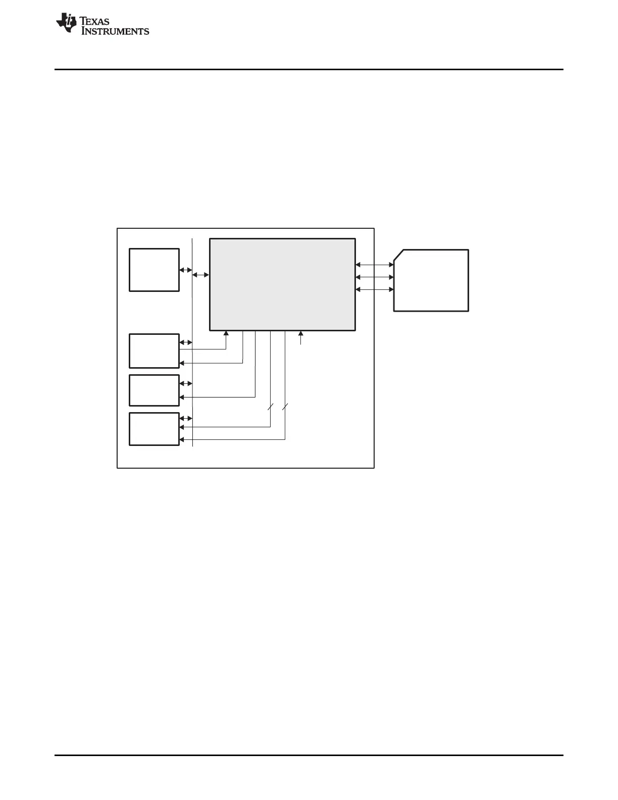
24.3.2.12 3- or 4-Pin Mode
External SPI bus interface can be configured to use a restricted set of pin using the bit field
MCSPI_MODULCTRL[PIN34] and depending on targeted application:
• If MCSPI_MODULCTRL[PIN34] is cleared to 0 (default value) the controller is in 4-pin mode using the
SPI pins CLKSPI, SOMI, SIMO and chip enable CS.
• If MCSPI_MODULCTRL[PIN34] is set to 1 the controller is in 3-pin mode using the SPI pins CLKSPI,
SOMI and SIMO.
In 3-pin mode it is mandatory to put the controller in single channel master mode
(MCSPI_MODULECTRL[SINGLE] asserted) and to connect only one SPI device on the bus.
Figure 24-22. 3-Pin Mode System Overview
In 3-pin mode all options related to chip select management are useless:
• MCSPI_CHxCONF[EPOL]
• MCSPI_CHxCONF[TCS0]
• MCSPI_CHxCONF[FORCE]
The chip select pin SPIEN is forced to ‘0’ in this mode.
4021
SPRUH73H–October 2011–Revised April 2013 Multichannel Serial Port Interface (McSPI)
Submit Documentation Feedback
Copyright © 2011–2013, Texas Instruments Incorporated

 Loading...


