www.ti.com
GPMC
7.1.5.11 GPMC_CONFIG1_i
The configuration 1 register sets signal control parameters per chip select.
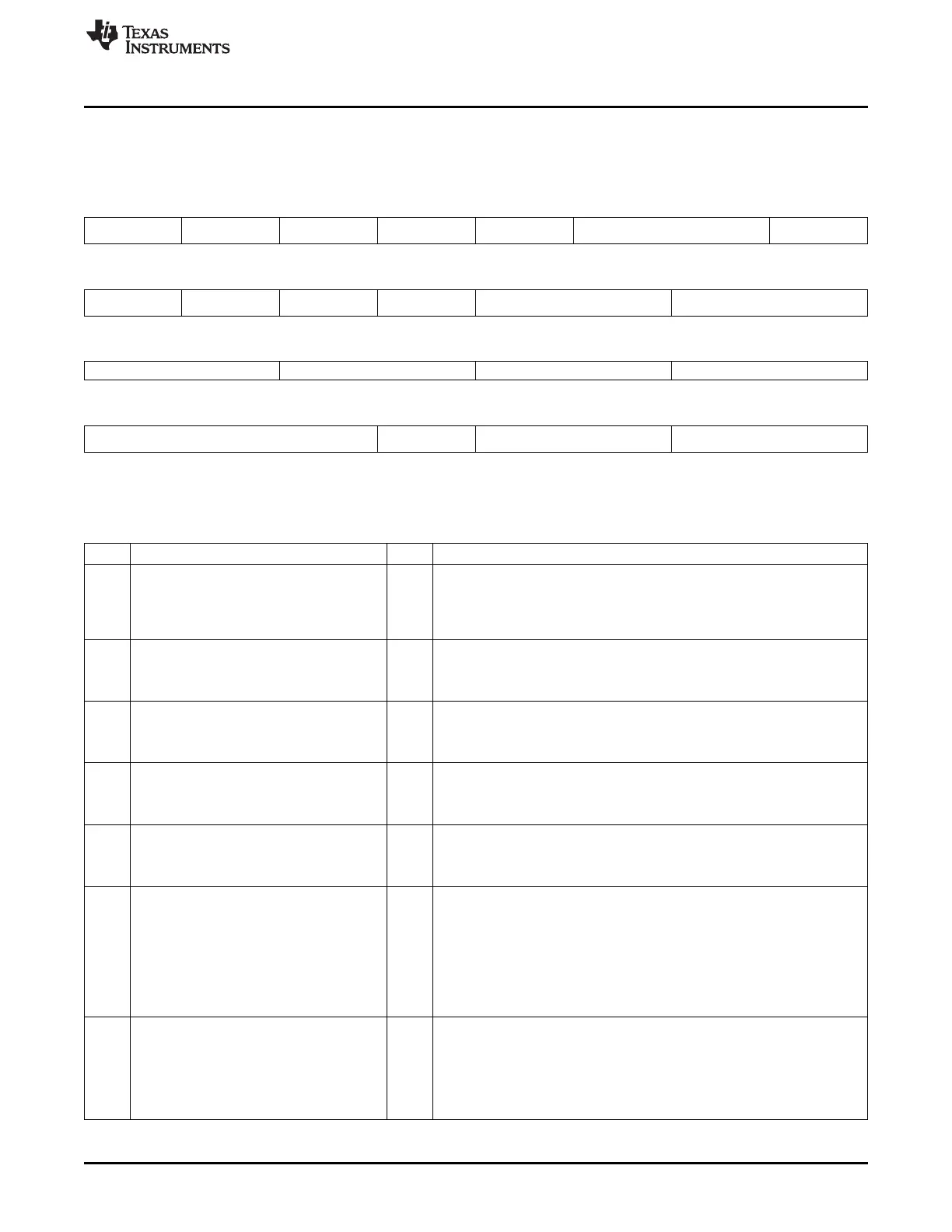
Figure 7-61. GPMC_CONFIG1_i
31 30 29 28 27 26 25 24
WRAPBURST READMULTIPLE READTYPE WRITEMULTIPLE WRITETYPE CLKACTIVATIONTIME ATTACHEDDEVICE
PAGELENGTH
R/W-0 R/W-0 R/W-0 R/W-0 R/W-0 R/W-0 R/W-0
23 22 21 20 19 18 17 16
ATTACHEDDEVICE WAITREADMONITOR WAITWRITEMONITO Reserved WAITMONITORINGTIME WAITPINSELECT
PAGELENGTH ING RING
R/W-0 R/W-0 R/W-0 R-0 R/W-0 R/W-0
15 14 13 12 11 10 9 8
Reserved DEVICESIZE DEVICETYPE MUXADDDATA
R-0 R/W-0 R/W-0 R/W-0
7 5 4 3 2 1 0
Reserved TIMEPARA Reserved GPMCFCLKDIVIDER
GRANULARITY
R-0 R/W-0 R-0 R/W-0
LEGEND: R = Read only; W1C = Write 1 to clear bit; -n = value after reset
Table 7-65. GPMC_CONFIG1_i Field Descriptions
Bit Field Value Description
31 WRAPBURST Enables the wrapping burst capability. Must be set if the attached device is
configured in wrapping burst
0 Synchronous wrapping burst not supported
1 Synchronous wrapping burst supported
30 READMULTIPLE Selects the read single or multiple access
0 single access
1 multiple access (burst if synchonous, page if asynchronous)
29 READTYPE Selects the read mode operation
0 Read Asynchronous
1 Read Synchronous
28 WRITEMULTIPLE Selects the write single or multiple access
0 Single access
1 Multiple access (burst if synchronous, considered as single if asynchronous)
27 WRITETYPE Selects the write mode operation
0 Write Asynchronous
1 Write Synchronous
26-25 CLKACTIVATIONTIME Output GPMC.CLK activation time
0 First rising edge of GPMC_CLK at start access time
1h First rising edge of GPMC_CLK one GPMC_FCLK cycle after start access
time
2h First rising edge of GPMC_CLK two GPMC_FCLK cycles after start access
time
3h Reserved
24-23 ATTACHEDDEVICEPAGELENGTH Specifies the attached device page (burst) length (1 Word = Interface size)
0 4 Words
1h 8 Words
2h 16 Words
3h Reserved
375
SPRUH73H–October 2011–Revised April 2013 Memory Subsystem
Submit Documentation Feedback
Copyright © 2011–2013, Texas Instruments Incorporated

 Loading...


