www.ti.com
McASP Registers
22.4.1.2 Power Idle SYSCONFIG Register (PWRIDLESYSCONFIG)
The PWRIDLESYSCONFIG is shown in Figure 22-40 and described in Table 22-13.
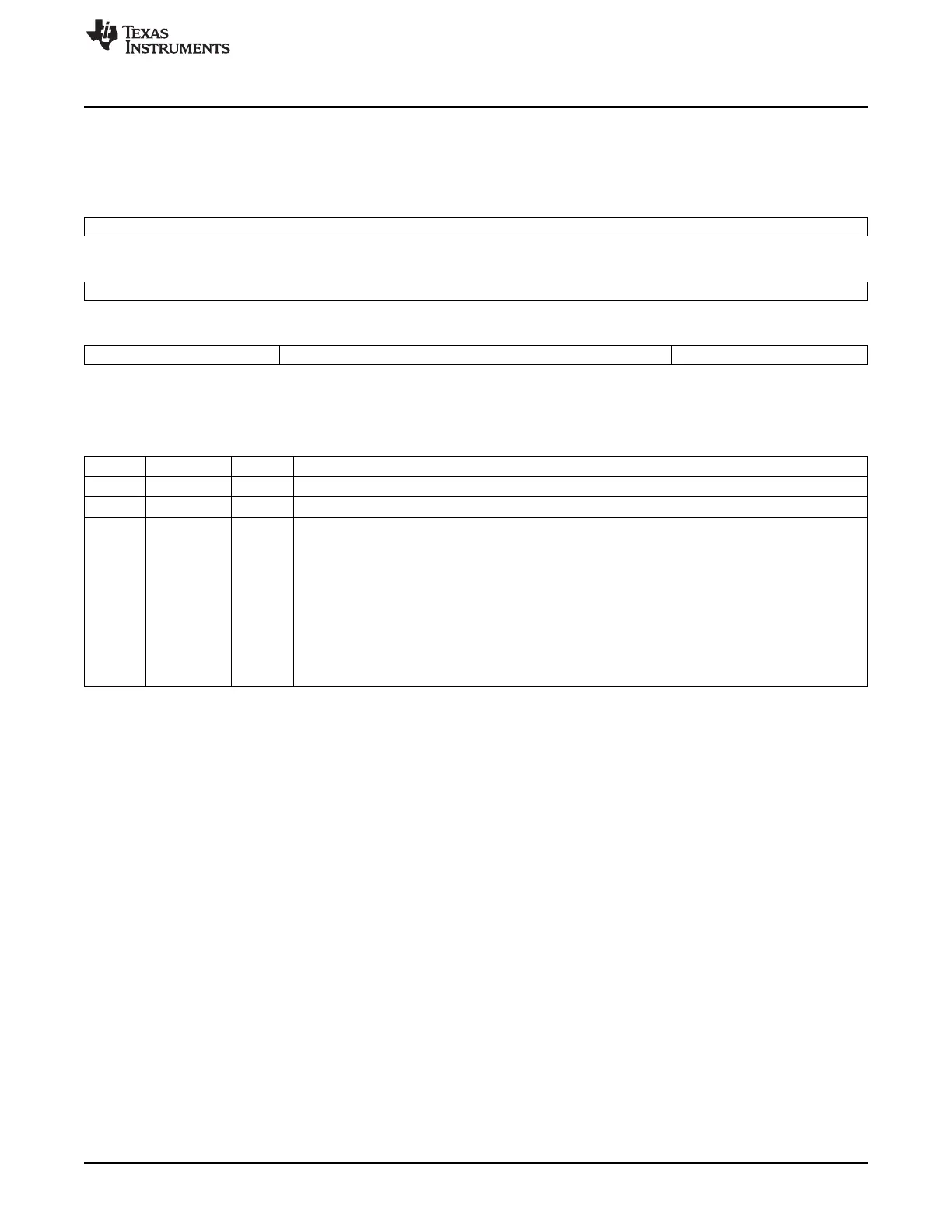
Figure 22-40. Power Idle SYSCONFIG Register (PWRIDLESYSCONFIG)
31 30 29 28 27 26 25 24
Reserved
R-0
23 8
Reserved
R-0
7 6 5 4 3 2 1 0
Reserved Other IDLEMODE
R-0 R/W-0 R/W-10
LEGEND: R/W = Read/Write; R = Read only; -n = value after reset
Table 22-13. Power Idle SYSCONFIG Register (PWRIDLESYSCONFIG) Field Descriptions
Bit Field Value Description
31-6 Reserved 0 Reserved.
5-2 Other 0 Reserved for future programming.
1-0 IDLEMODE 10b
Power management Configuration of the local target state management mode.
By definition, target can handle read/write transaction as long as it is out of IDLE state.
0x0 = Force-idle mode: local target's idle state follows (acknowledges) the system's idle requests
unconditionally, i.e. regardless of the IP module's internal requirements. Backup mode, for debug
only.
0x1 = No-idle mode: local target never enters idle state. Backup mode, for debug only.
0x2 = Smart-idle mode: local target's idle state eventually follows (acknowledges) the system's idle
requests, depending on the IP module's internal requirements. IP module shall not generate (IRQ- or
DMA-request-related) wakeup events.
0x3 = Reserved.
3829
SPRUH73H–October 2011–Revised April 2013 Multichannel Audio Serial Port (McASP)
Submit Documentation Feedback
Copyright © 2011–2013, Texas Instruments Incorporated

 Loading...


