www.ti.com
Multimedia Card Registers
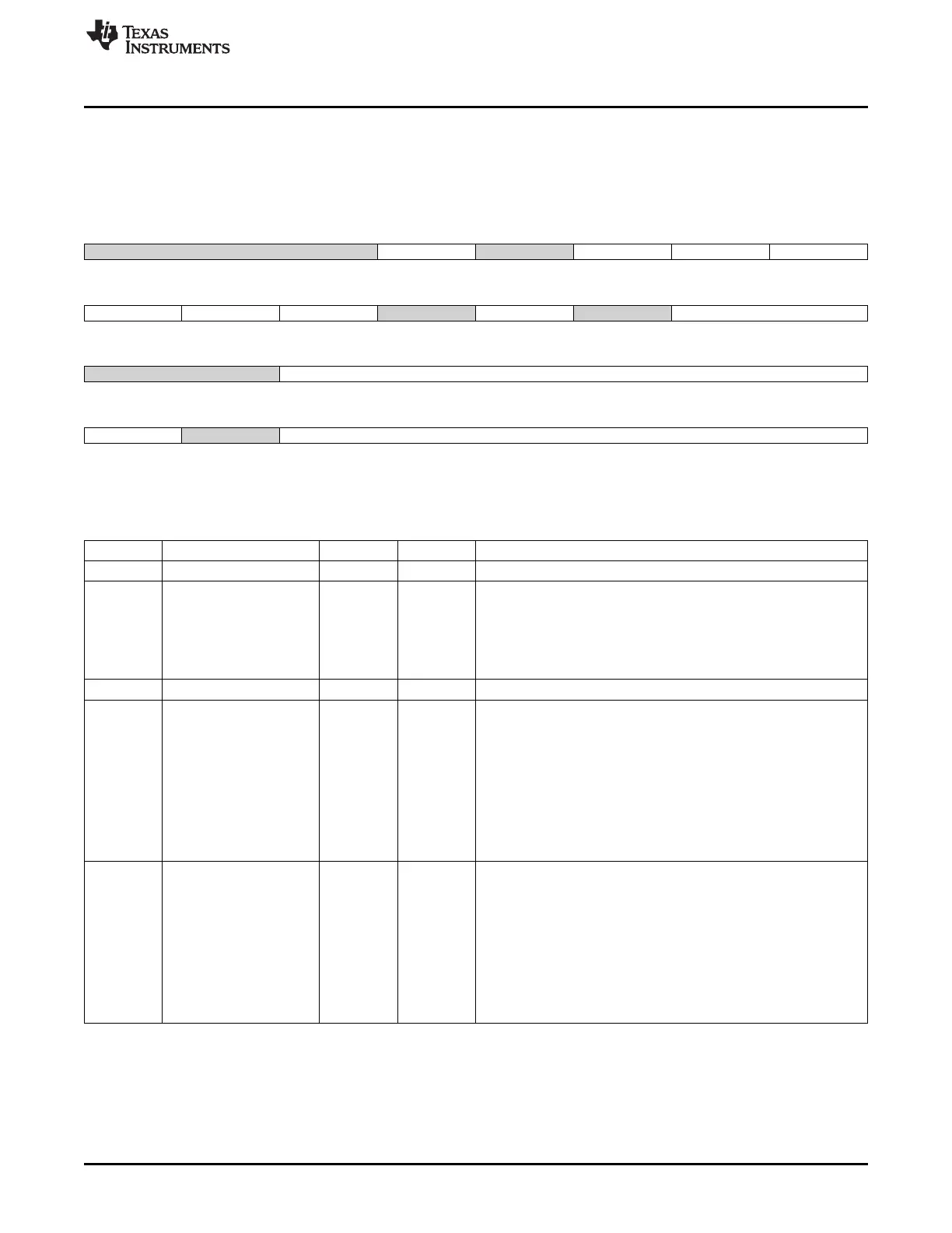
18.5.1.23 SD_CAPA Register (offset = 240h) [reset = 0h]
SD_CAPA is shown in Figure 18-59 and described in Table 18-42.
This register lists the capabilities of the MMC/SD/SDIO host controller.
Figure 18-59. SD_CAPA Register
31 30 29 28 27 26 25 24
Reserved BUS_64BIT Reserved VS18 VS30 VS33
R-0h R/W-0h R-0h R/W-0h R/W-0h R/W-0h
23 22 21 20 19 18 17 16
SRS DS HSS Reserved AD2S Reserved MBL
R-0h R-0h R-0h R-0h R-0h R-0h R-0h
15 14 13 12 11 10 9 8
Reserved BCF
R-0h R-0h
7 6 5 4 3 2 1 0
TCU Reserved TCF
R-0h R-0h R-0h
LEGEND: R/W = Read/Write; R = Read only; W1toCl = Write 1 to clear bit; -n = value after reset
Table 18-42. SD_CAPA Register Field Descriptions
Bit Field Type Reset Description
31-29 Reserved R 0h
28 BUS_64BIT R/W 0h 64 Bit System Bus Support.
Setting 1 to this bit indicates that the Host Controller supports
64-bit address descriptor mode and is connected to
64-bit address system bus.
0x0(R) = 32-bit System bus address
0x1(R) = 64-bit System bus address
27 Reserved R 0h
26 VS18 R/W 0h Voltage support 1.8 V.
Initialization of this register (via a write access to this register)
depends on the system capabilities.
The host driver shall not modify this register after the initialization.
This register is only reinitialized by a hard reset (via mmc_RESET
signal).
0x0(W) = 1.8 V not supported
0x0(R) = 1.8 V not supported
0x1(W) = 1.8 V supported
0x1(R) = 1.8 V supported
25 VS30 R/W 0h Voltage support 3.0V.
Initialization of this register (via a write access to this register)
depends on the system capabilities.
The host driver shall not modify this register after the initialization.
This register is only reinitialized by a hard reset (via mmc_RESET
signal).
0x0(W) = 3.0 V not supported
0x0(R) = 3.0 V not supported
0x1(W) = 3.0 V supported
0x1(R) = 3.0 V supported
3437
SPRUH73H–October 2011–Revised April 2013 Multimedia Card (MMC)
Submit Documentation Feedback
Copyright © 2011–2013, Texas Instruments Incorporated

 Loading...


