www.ti.com
CONTROL_MODULE Registers
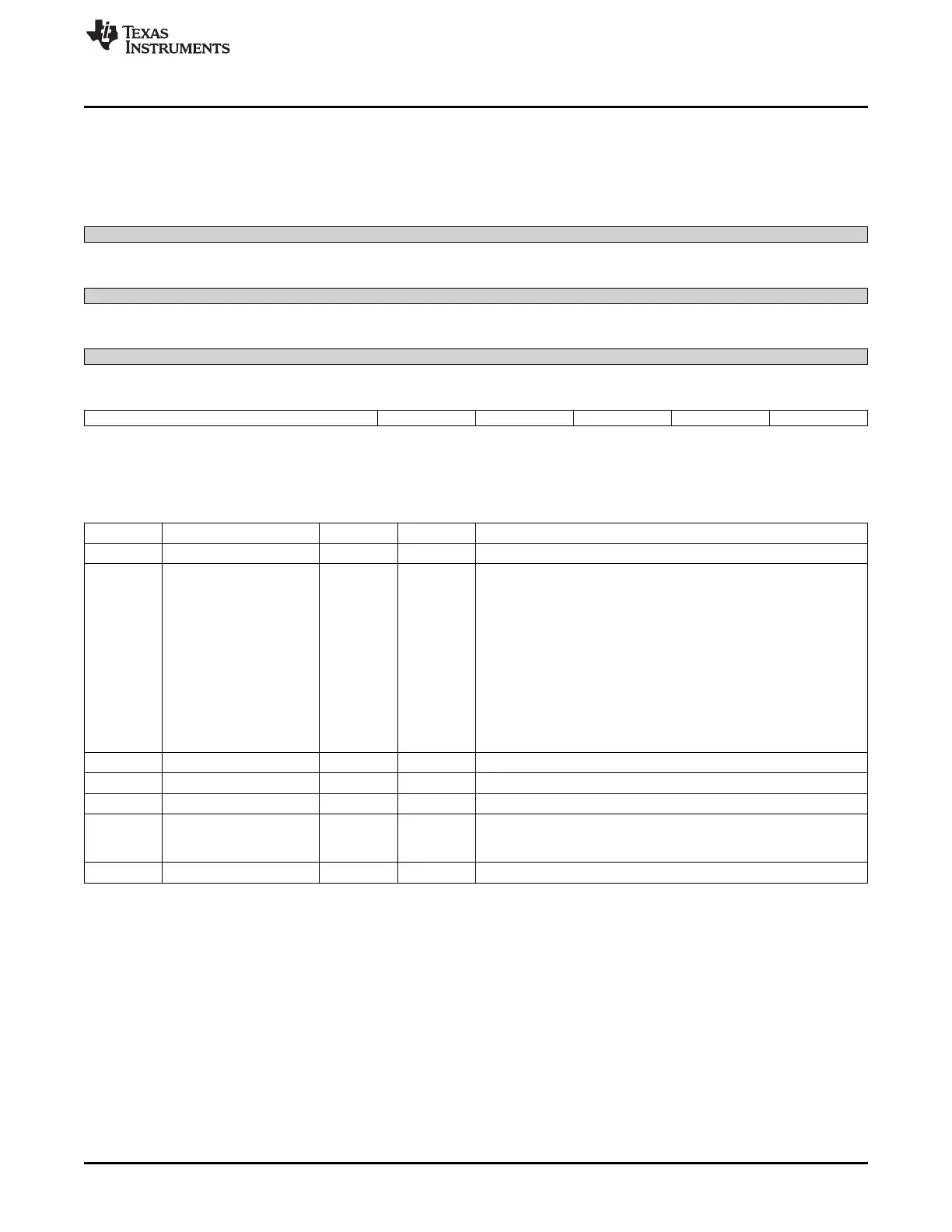
9.3.22 usb_sts0 Register (offset = 624h) [reset = 0h]
usb_sts0 is shown in Figure 9-25 and described in Table 9-32.
Figure 9-25. usb_sts0 Register
31 30 29 28 27 26 25 24
Reserved
R-0h
23 22 21 20 19 18 17 16
Reserved
R-0h
15 14 13 12 11 10 9 8
Reserved
R-0h
7 6 5 4 3 2 1 0
chgdetsts cdet_dmdet cdet_dpdet cdet_datadet chgdetect chgdetdone
R-0h R-0h R-0h R-0h R-0h R-0h
LEGEND: R/W = Read/Write; R = Read only; W1toCl = Write 1 to clear bit; -n = value after reset
Table 9-32. usb_sts0 Register Field Descriptions
Bit Field Type Reset Description
31-8 Reserved R 0h
7-5 chgdetsts R 0h Charge Detection Status
000: Wait State (When a D+WPU and D-15K are connected, it
enters into this state and will remain in this state unless it enters into
other state)
001: No Contact
010: PS/2
011: Unknown error
100: Dedicated charger(valid if CE is HIGH)
101: HOST charger (valid if CE is HIGH)
110: PC
111: Interrupt (if any of the pullup is enabled, charger detect routine
gets interrupted and will restart from the beginning if the same is
disabled)
4 cdet_dmdet R 0h DM Comparator Output
3 cdet_dpdet R 0h DP Comparator Output
2 cdet_datadet R 0h Charger Comparator Output
1 chgdetect R 0h Charger Detection Status
0: Charger was no detected
1: Charger was detected
0 chgdetdone R 0h Charger Detection Protocol Done
785
SPRUH73H–October 2011–Revised April 2013 Control Module
Submit Documentation Feedback
Copyright © 2011–2013, Texas Instruments Incorporated

 Loading...


