CTR = CMPB
CTR = CMPA
CTR_Dir
CTR = 0
CTR = PRD
Dead
Band
(DB)
Counter
Compare
(CC)
Action
Qualifier
(AQ)
EPWMxA
EPWMxB
CTR = CMPB
CTR = 0
EPWMxINT
EPWMxA
EPWMxB
TZ1
to TZn
CTR = CMPA
Time-Base
(TB)
CTR = PRD
CTR = 0
CTR_Dir
EPWMxSYNCI
EPWMxSYNCO
EPWMxTZINT
PWM-
chopper
(PC)
Event
Trigger
and
Interrupt
(ET)
Trip
Zone
(TZ)
GPIO
MUX
Interrupt
controller
Interrupt
controller
www.ti.com
Enhanced PWM (ePWM) Module
Example 15-1. Constant Definitions Used in the Code Examples (continued)
#define ET_CTRD_CMPB 0x7
// ETPS (Event-trigger Prescale)
// = = = = = = = = = = = = = = = = = = = = = = = = = =
// INTPRD, SOCAPRD, SOCBPRD bits
#define ET_DISABLE 0x0
#define ET_1ST 0x1
#define ET_2ND 0x2
#define ET_3RD 0x3
15.2.2.2 Proper Interrupt Initialization Procedure
When the ePWM peripheral clock is enabled it may be possible that interrupt flags may be set due to
spurious events due to the ePWM registers not being properly initialized. The proper procedure for
initializing the ePWM peripheral is:
1. Disable global interrupts (CPU INTM flag)
2. Disable ePWM interrupts
3. Initialize peripheral registers
4. Clear any spurious ePWM flags
5. Enable ePWM interrupts
6. Enable global interrupts
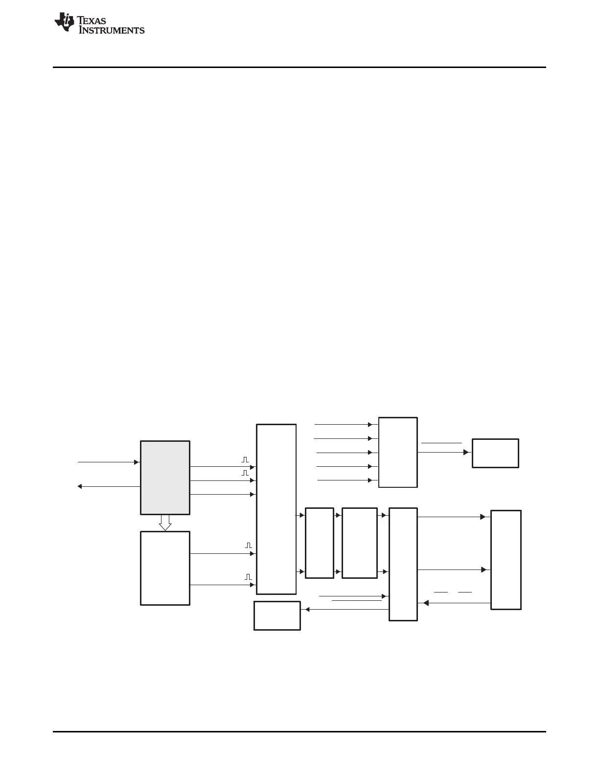
15.2.2.3 Time-Base (TB) Submodule
Each ePWM module has its own time-base submodule that determines all of the event timing for the
ePWM module. Built-in synchronization logic allows the time-base of multiple ePWM modules to work
together as a single system. Figure 15-9 illustrates the time-base module's place within the ePWM.
Figure 15-9. Time-Base Submodule Block Diagram
1501
SPRUH73H–October 2011–Revised April 2013 Pulse-Width Modulation Subsystem (PWMSS)
Submit Documentation Feedback
Copyright © 2011–2013, Texas Instruments Incorporated

 Loading...


