LCD Registers
www.ti.com
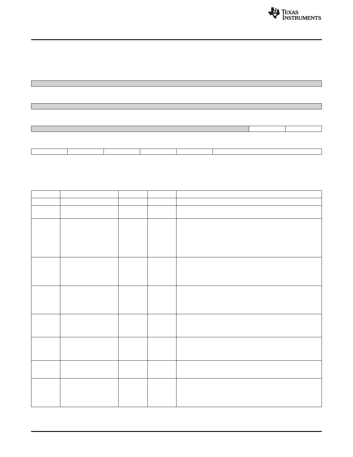
13.5.3 LIDD_CTRL Register (offset = Ch) [reset = 0h]
LIDD_CTRL is shown in Figure 13-21 and described in Table 13-16.
Figure 13-21. LIDD_CTRL Register
31 30 29 28 27 26 25 24
Reserved
R-0h
23 22 21 20 19 18 17 16
Reserved
R-0h
15 14 13 12 11 10 9 8
Reserved dma_cs0_cs1 lidd_dma_en
R-0h R/W-0h R/W-0h
7 6 5 4 3 2 1 0
cs1_e1_pol cs0_e0_pol ws_dir_pol rs_en_pol alepol lidd_mode_sel
R/W-0h R/W-0h R/W-0h R/W-0h R/W-0h R/W-0h
LEGEND: R/W = Read/Write; R = Read only; W1toCl = Write 1 to clear bit; -n = value after reset
Table 13-16. LIDD_CTRL Register Field Descriptions
Bit Field Type Reset Description
31-10 Reserved R 0h
9 dma_cs0_cs1 R/W 0h CS0/CS1 Select for LIDD DMA writes
0 = DMA writes to LIDD CS0 1 = DMA writes for LIDD CS1
8 lidd_dma_en R/W 0h LIDD DMA Enable 0 = Deactivate DMA control of LIDD interface
DMA control is released upon completion of transfer of the current
frame of data (LIDD Frame Done) after this bit is cleared
The MPU has direct read/write access to the panel in this mode
1 = Activate DMA to drive LIDD interface to support streaming data
to smart panels
The MPU cannot access the panel directly in this mode
7 cs1_e1_pol R/W 0h Chip Select 1/Enable 1 (Secondary) Polarity Control 0 = Do Not
Invert Chip Select 1/Enable 1
Chip Select 1 is active low by default
Enable 1 is active high by default
1 = Invert Chip Select 1/Enable 1
6 cs0_e0_pol R/W 0h Chip Select 0/Enable 0 (Secondary) Polarity Control
0 = Do Not Invert Chip Select 0/Enable 0
Chip Select 0 is active low by default
Enable 0 is active high by default
1 = Invert Chip Select 0/Enable 0
5 ws_dir_pol R/W 0h Write Strobe/Direction Polarity Control 0 = Do Not Invert Write
Strobe/Direction
Write Strobe/Direction is active low/write low by default
1 = Invert Write Strobe/Direction
4 rs_en_pol R/W 0h Read Strobe/Direction Polarity Control
0 = Do Not Invert Read Strobe/Direction
Read Strobe/Direction is active low/write low by default
1 = Invert Read Strobe/Direction
3 alepol R/W 0h Address Latch Enable (ALE) Polarity Control 0 = Do Not Invert ALE
ALE is active low by default
1 = Invert
2-0 lidd_mode_sel R/W 0h LIDD Mode Select
Selects type of LCD display interface for the LIDD to drive: 000b =
Sync MPU68 001b = Async MPU68 010b = Sync MPU80 011b =
Async MPU80 100b = Hitachi (Async) 101b = N/A 110b = N/A 111b
= N/A
1132
LCD Controller SPRUH73H–October 2011–Revised April 2013
Submit Documentation Feedback
Copyright © 2011–2013, Texas Instruments Incorporated

 Loading...


