www.ti.com
Interrupt Controller Registers
6.5.1.8 INTC_IDLE Register (offset = 50h) [reset = 0h]
INTC_IDLE is shown in Figure 6-11 and described in Table 6-11.
This register controls the clock auto-idle for the functional clock and the input synchronisers
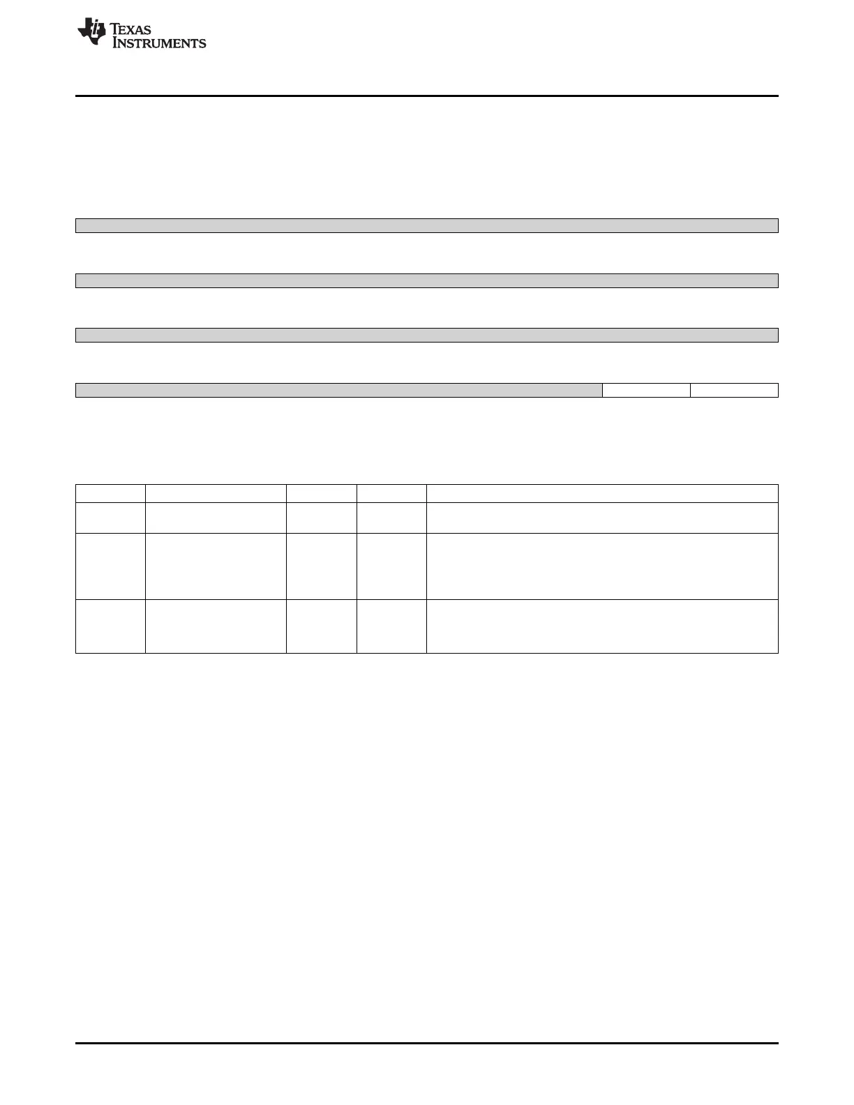
Figure 6-11. INTC_IDLE Register
31 30 29 28 27 26 25 24
Reserved
R-0h
23 22 21 20 19 18 17 16
Reserved
R-0h
15 14 13 12 11 10 9 8
Reserved
R-0h
7 6 5 4 3 2 1 0
Reserved Turbo FuncIdle
R-0h R/W-0h R/W-0h
LEGEND: R/W = Read/Write; R = Read only; W1toCl = Write 1 to clear bit; -n = value after reset
Table 6-11. INTC_IDLE Register Field Descriptions
Bit Field Type Reset Description
31-2 Reserved R 0h Write 0's for future compatibility.
Reads returns 0
1 Turbo R/W 0h
Input synchroniser clock auto-gating
0x0 = SyncFree : Input synchroniser clock is free running (default)
0x1 = SyncAuto : Input synchroniser clock is auto-gated based on
interrupt input activity
0 FuncIdle R/W 0h
Functional clock auto-idle mode
0x0 = FuncAuto : Functional clock gating strategy is applied (default)
0x1 = FuncFree : Functional clock is free-running
213
SPRUH73H–October 2011–Revised April 2013 Interrupts
Submit Documentation Feedback
Copyright © 2011–2013, Texas Instruments Incorporated

 Loading...


