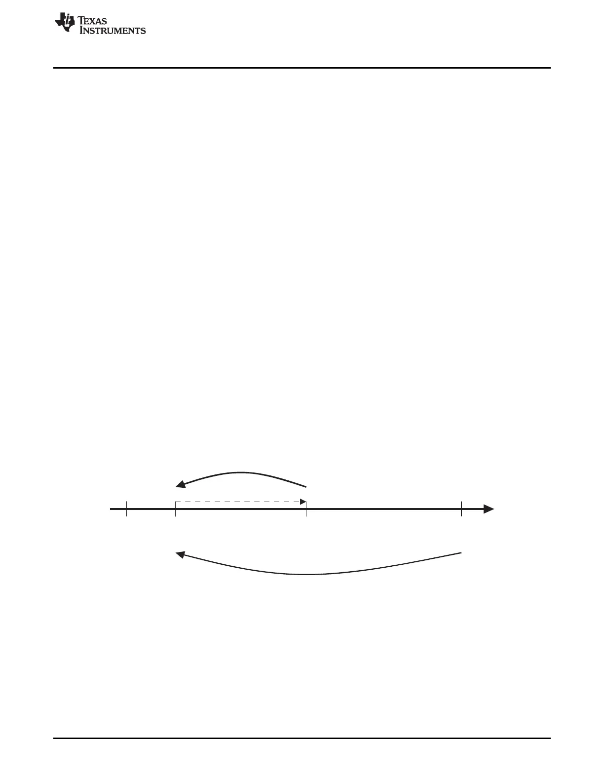
Load register
(TLDR)
Counter register
(T CRR)
Auto -relo ad on
(TCLR (AR) =”1”)
0xFFFF FFFF
Overf lo w
pulse is generated
Trig R eg is te r
(TTGR)
0x0000 0000
www.ti.com
DMTimer 1ms
20.2.3 Functional Description
The general-purpose timer is an upward counter. It supports 3 functional modes:
• Timer mode
• Capture mode
• Compare mode
By default, after core reset, the capture and compare modes are disabled.
20.2.3.1 Timer Mode Functionality
The timer is an upward counter that can be started and stopped at any time through the Timer Control
Register (TCLR ST bit). The Timer Counter Register (TCRR) can be loaded when stopped or on the fly
(while counting). TCRR can be loaded directly by a TCRR Write access with the new timer value. TCRR
can also be loaded with the value held in the Timer Load Register TLDR by a trigger register (TTGR)
Write access. The TCRR loading is done regardless the TTGR written value. The timer counter register
TCRR value can be read when stopped or captured on the fly by a TCRR Read access. The timer is
stopped and the counter value set to “0” when the module’s reset is asserted. The timer is maintained in
stop after reset is released. When the timer is stopped TCRR is frozen and it can be restarted from the
frozen value unless TCRR has been reloaded with a new value.
In the one shot mode (TCLR AR bit =”0”), the counter is stopped after counting overflow (counter value
remains at zero).
When the auto-reload mode is enabled (TCLR AR bit =”1”), the TCRR is reloaded with the Timer Load
Register (TLDR) value after a counting overflow.
It is not recommended to put the overflow value (0xFFFFFFFF) in TLDR because it can lead to undesired
results.
An interrupt can be issued on overflow if the overflow interrupt enable bit is set in the timer Interrupt
Enable Register (TIER OVF_IT_ENA bit =”1”). A dedicated output pin (PORTIMERPWM) is programmed
through TCLR (TRG and PT bits) to generate one positive pulse (prescaler duration) or to invert the
current value (toggle mode) when an overflow occurs.
Figure 20-28. TCRR Timing Value
20.2.3.1.1 1 ms Tick Generation
To minimize the error between a true 1ms tick and the tick generated by the 32768 Hz timer the
sequencing of the sub-1ms periods and the over-1ms periods must be shuffled.
An additional block (1ms block) is used to correct this error.
In this implementation the increment sequencing is automatically managed by the timer to minimize the
error. The value of the Timer Positive Increment register (TPIR) and Timer Negative Increment register
(TNIR) only need to be defined by the user. Auto adaptation mechanism is used to simplify the
programming model.
3589
SPRUH73H–October 2011–Revised April 2013 Timers
Submit Documentation Feedback
Copyright © 2011–2013, Texas Instruments Incorporated

 Loading...


