www.ti.com
LCD Registers
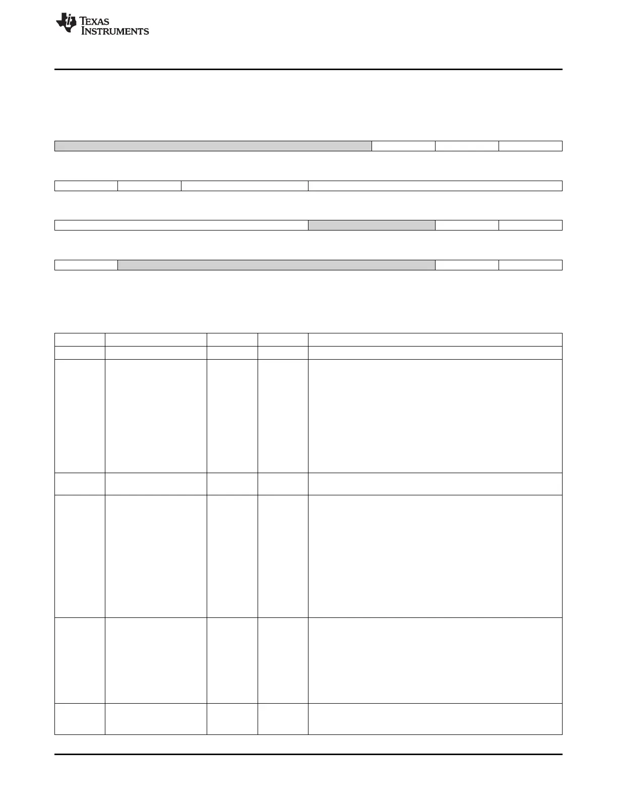
13.5.10 RASTER_CTRL Register (offset = 28h) [reset = 0h]
RASTER_CTRL is shown in Figure 13-28 and described in Table 13-23.
Figure 13-28. RASTER_CTRL Register
31 30 29 28 27 26 25 24
Reserved tft24unpacked tft24 stn565
R/W-0h R/W-0h R/W-0h R/W-0h
23 22 21 20 19 18 17 16
tftmap nibmode palmode reqdly
R/W-0h R/W-0h R/W-0h R/W-0h
15 14 13 12 11 10 9 8
reqdly Reserved nono8b rdorder
R/W-0h R/W-0h R/W-0h R/W-0h
7 6 5 4 3 2 1 0
lcdtft Reserved lcdbw lcden
R/W-0h R/W-0h R/W-0h R/W-0h
LEGEND: R/W = Read/Write; R = Read only; W1toCl = Write 1 to clear bit; -n = value after reset
Table 13-23. RASTER_CTRL Register Field Descriptions
Bit Field Type Reset Description
31-27 Reserved R/W 0h
26 tft24unpacked R/W 0h 24 bit Mode Packing Only used when cfg_tft24=1 and cfg_lcdtft=1
0: 24-bit pixels are packed into 32 bit boundaries, which means 4
pixels are saved in every three words
Word 0: pix1[7:0], pix0[23:0]
Word 1: pix2[15:0], pix1[23:8]
Word 2: pix3[23:0], pix2[23:16]
1: 24-bit pixels are stored unpacked in with the uppermost byte
unused
Word 0: Unused[7:0], pix0[23:0]
Word 1: Unused[7:0], pix1[23:0]
Word 2: Unused[7:0], pix2[23:0]
Word3: Unused[7:0], pix3[23:0]
25 tft24 R/W 0h 24 bit mode 0 = off 1 = on (24-bit data in active mode) The format of
the framebuffer data depends on cfg_tft24unpacked
24 stn565 R/W 0h Passive Matrix Mode only (cfg_lcdtft='0') and 16 bpp raw data
framebuffers (bpp = ?00?
If the bpp field in the framebuffer palette header is ?00?(12/16/24
bpp source), then the DDR contains raw data and the palette lookup
is bypassed
Only for this case, this bit selects whether the framebuffer format is
16 bpp 565 or 12 bpp
The Grayscaler can only take 12 bits per pixel
The framebuffer data is 16 bits per pixel 565 when stn565 is set to
`1' and only the 4 most significant bits of each color component are
sent to the Grayscaler input
0: Framebuffer is 12 bpp packed in bits [11:0] 1: Framebuffer is 16
bpp 565
23 tftmap R/W 0h TFT Mode Alternate Signal Mapping for Palettized framebuffer
Must be `0' for all 12/16/24 bpp raw data formats
Can only be `1' for 1/2/4/8 bpp Palette Lookup data
Valid only in Active Matrix mode when cfg_lcdtft='1'
0 = 4 bits per component output data for 1, 2, 4, and 8 bpp modes
will be right aligned on lcd_pins (11:0) 1 = 4 bits per component
output data for 1, 2, 4, and 8 bpp will be converted to 5,6,5, format
and use pins (15:0) R3 R2 R1 R0 R3 G3 G2 G1 G0 G3 G2 B3 B2
B1 B0 B3
22 nibmode R/W 0h Nibble Mode This bit is used to determine palette indexing and is
used in conjunction with cfg_rdorder
0: Nibble mode is disabled 1: Nibble mode is enabled
1139
SPRUH73H–October 2011–Revised April 2013 LCD Controller
Submit Documentation Feedback
Copyright © 2011–2013, Texas Instruments Incorporated

 Loading...


