( )
( )
0.1
2 13 1 0.1
s
x x s s
m
m m-
( )
( )
( )
( )
min 1, 2
2 13 _ 2
TSeg TSeg
x x bit time TSeg-
( )
( )
0.1
2 13 1 0.1
s
x x s s
m
m m-
( )
( )
( )
( )
min 1, 2
2 13 _ 2
TSeg TSeg
x x bit time TSeg-
Functional Description
www.ti.com
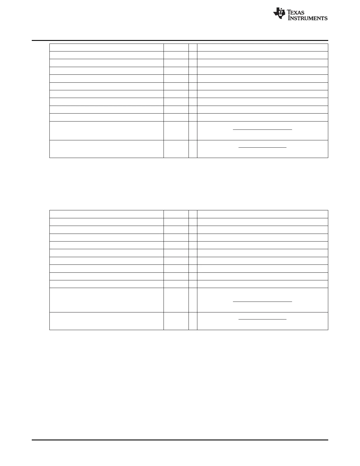
t
q
100 ns = t
CAN_CLK
delay of bus driver 60 ns =
delay of receiver circuit 40 ns =
delay of bus line (40 m) 220 ns =
t
Prop
700 ns = INT (2*delays + 1) = 7 • t
q
t
SJW
100 ns = 1 • t
q
t
TSeg1
800 ns = t
Prop
+ t
SJW
t
TSeg2
100 ns = Information Processing Time + 1 • t
q
t
Sync-Seg
100 ns = 1 • t
q
bit time 1000 ns = t
Sync-Seg
+ t
TSeg1
+ t
TSeg2
tolerance for CAN_CLK 0.43 % =
=
In this example, the concatenated bit time parameters are (1-1)
3
&(8-1)
4
&(1-1)
2
&(1-1)
6
, so the bit timing
register is programmed to = 00000700.
23.3.16.2.3 Example for Bit Timing at Low Baud Rate
In this example, the frequency of CAN_CLK is 2 MHz, BRP is 1, the bit rate is 100 KBit/s.
t
q
1 µs = t
CAN_CLK
Delay of bus driver 200 ns =
Delay of receiver circuit 80 ns =
Delay of bus line (40 m) 220 ns =
t
Prop
1 µs = 1 • t
q
t
SJW
4 µs = 4 • t
q
t
TSeg1
5 µs = t
Prop
+ t
SJW
t
TSeg2
3 µs = Information Processing Time + 3 • t
q
t
Sync-Seg
1 µs = 1 • t
q
Bit time 9 µs = t
Sync-Seg
+ t
TSeg1
+ t
TSeg2
Tolerance for CAN_CLK =
=
In this example, the concatenated bit time parameters are (3-1)
3
&(5-1)
4
&(4-1)
2
&(2-1)
6
, so the bit timing
register is programmed to = 0x000024C1.
3914
Controller Area Network (CAN) SPRUH73H–October 2011–Revised April 2013
Submit Documentation Feedback
Copyright © 2011–2013, Texas Instruments Incorporated

 Loading...


