Integration
www.ti.com
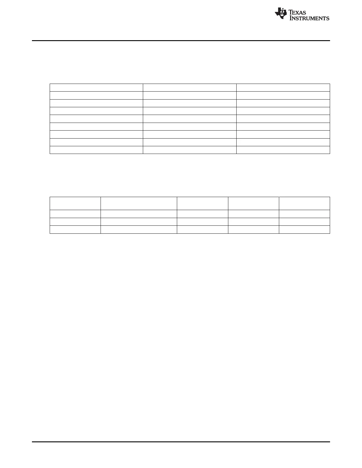
19.2.3 UART Pin List
The UART interface pins are listed in Table 19-8. Pin functionality depends on the selected operating
mode of the module.
Table 19-8. UART Pin List
Pin Type Description
UARTx_RXD / IRRX / RCRX I UART / IrDA / CIR Receive Data
UARTx_TXD / IRTX / RCTX OZ UART / IrDA / CIR Transmit Data
UARTx_RTSn / SD OZ UART Request to Send / IrDA Mode
UARTx_CTSn I UART Clear to Send
UARTx_DTRn
(1)
OZ UART Data Terminal Ready
UARTx_DSRn
(1)
I UART Data Set Ready
UARTx_DCDn
(1)
I UART Data Carrier Detect
UARTx_RIN
(1)
1 UART Ring Indicator
(1)
UART1 only
The UART module can operate in three different modes based on the MODE_SELECT bits. The signal
muxing based on these mode bits is shown in Table 19-9.
Table 19-9. UART Muxing Control
UARTx_TXD / IRTX / UARTx_RXD / IRRX / RCRX UARTx_RTSn / SD UARTx_CTSn Mode
RCTX Function Function Function Function
TXD RXD RTSn CTSn UART
IRTX IRRX SD not used IrDA (SIR, MIR, FIR)
RCTX RCRX SD not used CIR
3452
Universal Asynchronous Receiver/Transmitter (UART) SPRUH73H–October 2011–Revised April 2013
Submit Documentation Feedback
Copyright © 2011–2013, Texas Instruments Incorporated

 Loading...


