www.ti.com
Power, Reset, and Clock Management
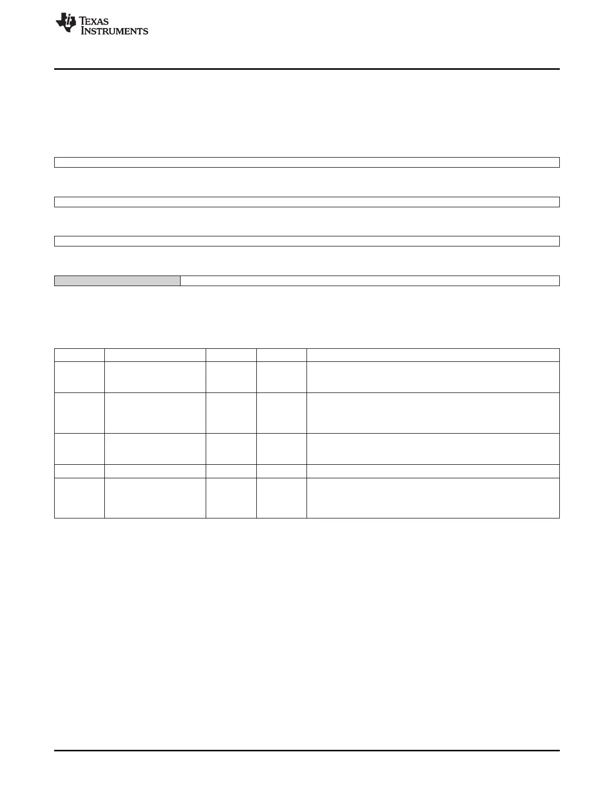
8.1.13.5.4 PRM_SRAM_COUNT Register (offset = Ch) [reset = 78000017h]
PRM_SRAM_COUNT is shown in Figure 8-182 and described in Table 8-201.
Common setup for SRAM LDO transition counters. Applies to all voltage domains. [warm reset insensitive]
Figure 8-182. PRM_SRAM_COUNT Register
31 30 29 28 27 26 25 24
StartUp_Count
R/W-78h
23 22 21 20 19 18 17 16
SLPCNT_VALUE
R/W-0h
15 14 13 12 11 10 9 8
VSETUPCNT_VALUE
R/W-0h
7 6 5 4 3 2 1 0
Reserved PCHARGECNT_VALUE
R-0h R/W-17h
LEGEND: R/W = Read/Write; R = Read only; W1toCl = Write 1 to clear bit; -n = value after reset
Table 8-201. PRM_SRAM_COUNT Register Field Descriptions
Bit Field Type Reset Description
31-24 StartUp_Count R/W 78h Determines the start-up duration of SRAM and ABB LDO.
The duration is computed as 16 x NbCycles of system clock cycles.
Target is 50us.
23-16 SLPCNT_VALUE R/W 0h Delay between retention/off assertion of last SRAM bank and
SRAMALLRET signal to LDO is driven high.
Counting on system clock.
Target is 2us.
15-8 VSETUPCNT_VALUE R/W 0h SRAM LDO rampup time from retention to active mode.
The duration is computed as 8 x NbCycles of system clock cycles.
Target is 30us.
7-6 Reserved R 0h
5-0 PCHARGECNT_VALUE R/W 17h Delay between de-assertion of standby_rta_ret_on and
standby_rta_ret_good.
Counting on system clock.
Target is 600ns.
729
SPRUH73H–October 2011–Revised April 2013 Power, Reset, and Clock Management (PRCM)
Submit Documentation Feedback
Copyright © 2011–2013, Texas Instruments Incorporated

 Loading...


