www.ti.com
Power, Reset, and Clock Management
The DPLL has two internal clocks:
• REFCLK (Internal reference clock): This is generated by dividing the input clock CLKINP by the
programmed value N+1. The entire loop of the PLL runs on the REFCLK.
Here, REFCLK = CLKINP/(N+1).
• BCLK: Bus clock which is used for programming the various settings using registers
The ADPLLS lock frequency is defined as follows: f
DPLL
= (M * CLKINP)/(N+1)
8.1.6.3.1 Clock Functions
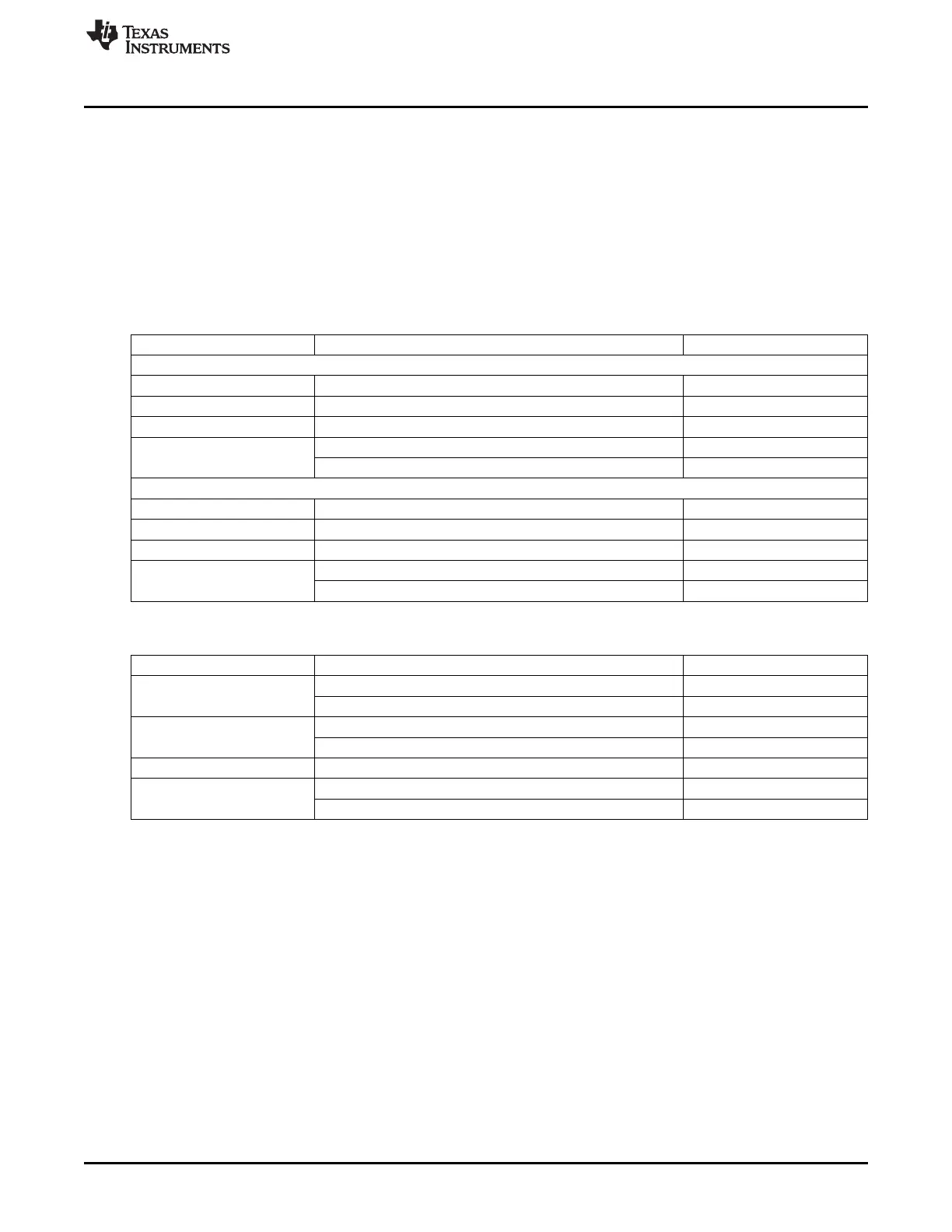
Table 8-17. Output Clocks in Locked Condition
Pin Name Frequency Comments
REGM4XEN='0'
CLKOUT [M / (N+1)] * CLKINP * [1/M2]
CLKOUTX2 2 * [M / (N+1)] * CLKINP * [1/M2]
CLKDCOLDO 2 * [M / (N+1)] * CLKINP
CLKINPHIF / M3 CLKINPHIFSEL='1'
CLKOUTHIF
2 * [M / (N+1)] * CLKINP * [1/M3] CLKINPHIFSEL='0'
REGM4XEN='1'
CLKOUT [4M / (N+1)] * CLKINP * [1/M2]
CLKOUTX2 2 * [4M / (N+1)] * CLKINP * [1/M2]
CLKDCOLDO 2 * [4M / (N+1)] * CLKINP
CLKINPHIF / M3 CLKINPHIFSEL='1'
CLKOUTHIF
2 * [4M / (N+1)] * CLKINP * [1/M3] CLKINPHIFSEL='0'
Table 8-18. Output Clocks Before Lock and During Relock Modes
Pin Name Frequency Comments
CLKINP / (N2+1) ULOWCLKEN='0'
CLKOUT
CLKINPULOW ULOWCLKEN='1'
CLKINP / (N2+1) ULOWCLKEN='0'
CLKOUTX2
CLKINPULOW ULOWCLKEN='1'
CLKDCOLDO Low
CLKINPHIF/M3 ULOWCLKEN='1'
CLKOUTHIF
Low ULOWCLKEN='0'
Note: Since M3 divider is running on the internal LDO domain, in the case when CLKINPHIFSEL=’1’,
CLKOUTHIF could be active only when internal LDO is ON. Hence, whenever LDOPWDN goes low to
high to powerdown LDO (happens when TINITZ activated / when entering slow relock bypass mode),
output CLKOUTHIF will glitch and stop. To avoid this glitch, it is recommended to gate CLKOUTHIF using
control CLKOUTHIFEN before asserting TINITZ / entering any slow relock bypass mode Frequency
Range (MHz)
See the device-specific data manual for details on operating performance points (OPPs) supported by
your device.
8.1.6.4 ADPLLLJ (Low Jitter DPLL)
The ADPLLLJ is a low jitter PLL with a 2-GHz maximum output. ADPLLLJ has a predivide feature which
allows user to divide, for instance, a 24-MHz or 26-MHz reference clock to 1 MHz and then multiply up to
2 GHz maximum.
All PLLs will come-up in bypass mode at reset. SW needs to program all the PLL settings appropriately
and then wait for PLL to be locked. For more details, see the configuration procedure for each PLL.
521
SPRUH73H–October 2011–Revised April 2013 Power, Reset, and Clock Management (PRCM)
Submit Documentation Feedback
Copyright © 2011–2013, Texas Instruments Incorporated

 Loading...


