www.ti.com
McSPI Registers
24.4.1.10 McSPI Channel (i) Control Register (MCSPI_CH(I)CTRL)
The McSPI channel i control register (MCSPI_CHiCTRL) is used to enable channel i. The
MCSPI_CHiCTRL is shown in Figure 24-35 and described in Table 24-21.
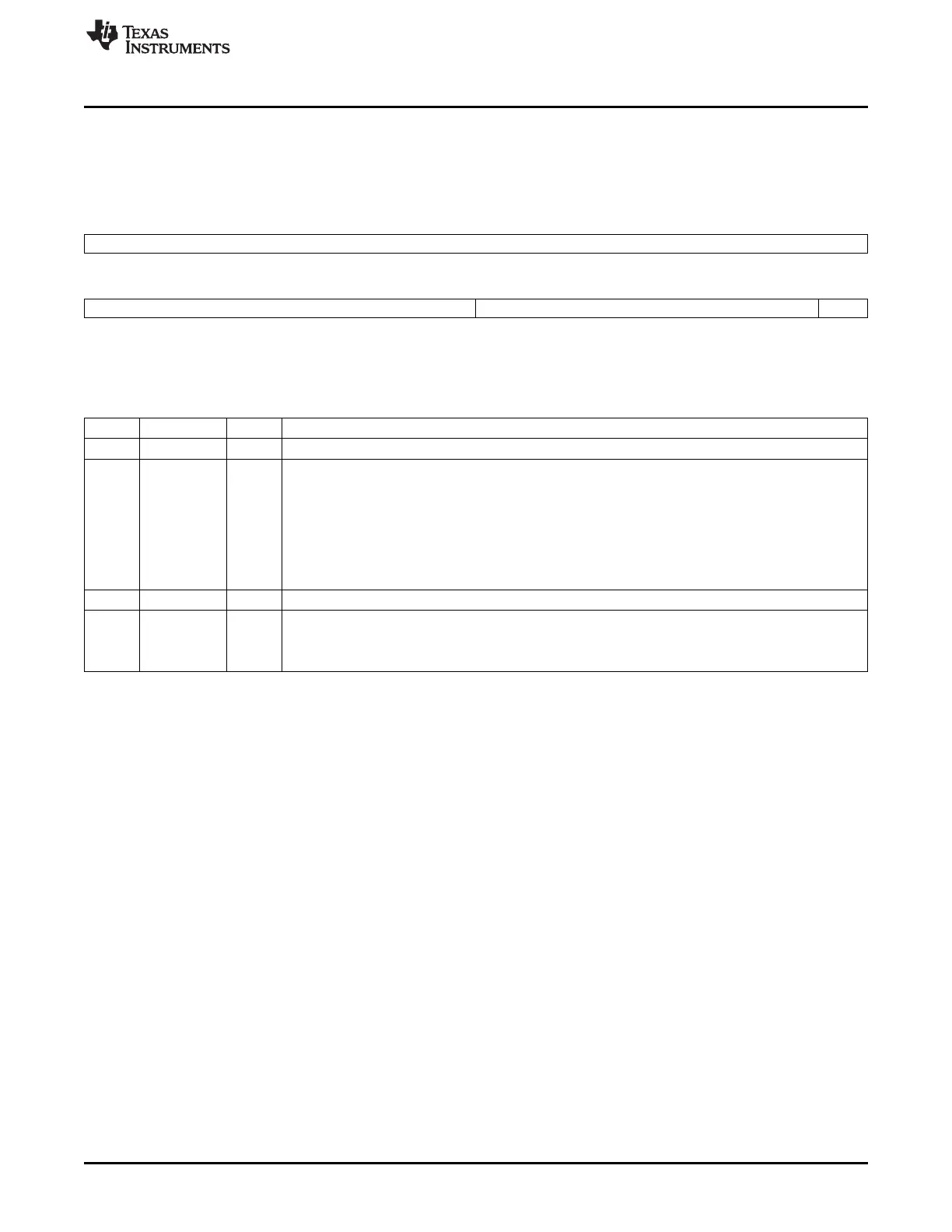
Figure 24-35. McSPI Channel (i) Control Register (MCSPI_CH(I)CTRL)
31 16
Reserved
R/W-0
15 8 7 1 0
EXTCLK Reserved EN
R/W-0 R/W-0 R/W-0
LEGEND: R/W = Read/Write; -n = value after reset
Table 24-21. McSPI Channel (i) Control Register (MCSPI_CH(I)CTRL) Field Descriptions
Bit Field Value Description
31-16 Reserved 0 Reserved
15-8 EXTCLK Clock ratio extension. Used to concatenate with the CLKD bit field in MCSPI_CHnCONF for clock ratio
only when granularity is 1 clock cycle (CLKG bit in MCSPI_CHnCONF set to 1). Then the maximum
value reached is a 4096 clock divider ratio.
0 Clock ratio is CLKD + 1
1h Clock ratio is CLKD + 1 + 16
... ...
FFh Clock ratio is CLKD + 1 + 4080
7-1 Reserved 0 Reserved
0 EN Channel n enable.
0 Channel n is not active.
1 Channel n is active.
4051
SPRUH73H–October 2011–Revised April 2013 Multichannel Serial Port Interface (McSPI)
Submit Documentation Feedback
Copyright © 2011–2013, Texas Instruments Incorporated

 Loading...


