Integration
www.ti.com
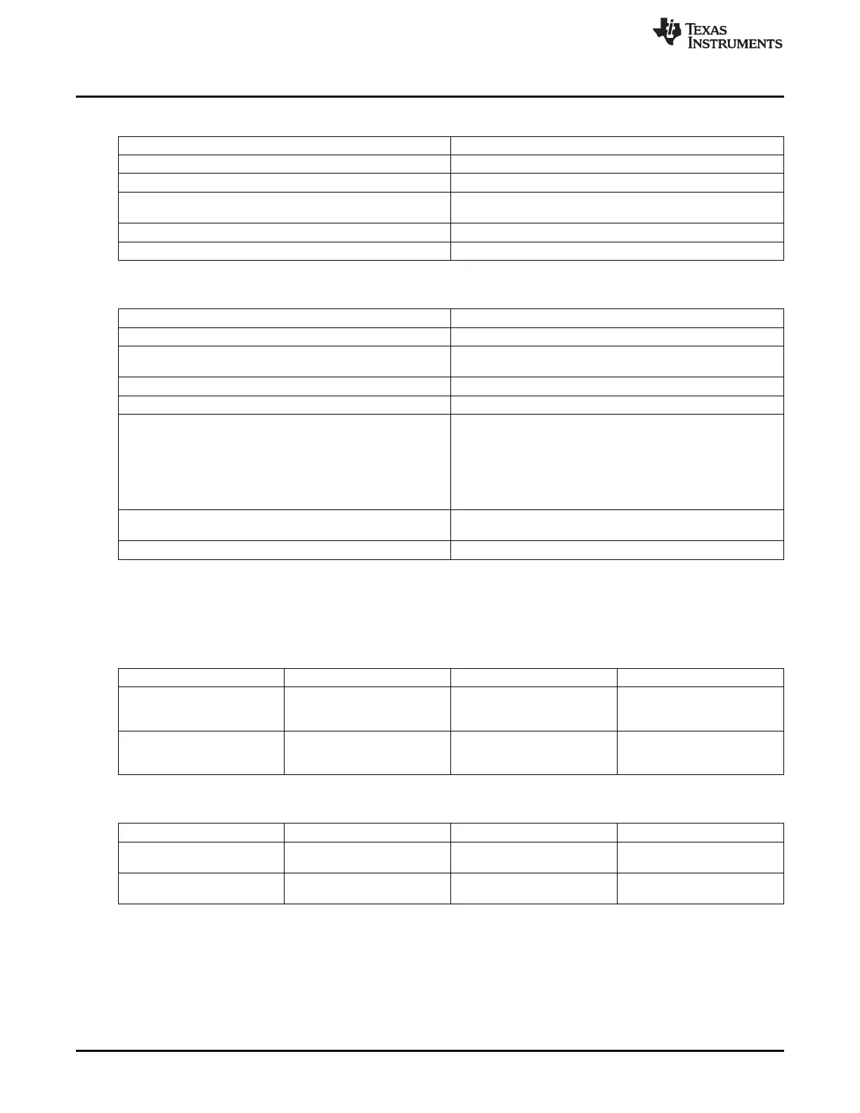
Table 19-2. UART0 Connectivity Attributes (continued)
Attributes Type
Reset Signals WKUP_DOM_RST_N
Idle/Wakeup Signals Smart Idle / Wakeup
Interrupt Requests 1 interrupt to MPU Subsystem (UART0INT), PRU-ICSS (nirq)
and WakeM3
DMA Requests 2 DMA requests to EDMA (TX – UTXEVT0, RX – URXEVT0)
Physical Address L4 Wakeup slave port
Table 19-3. UART1–5 Connectivity Attributes
Attributes Type
Power Domain Peripheral Domain
Clock Domain PD_PER_L4LS_GCLK (OCP)
PD_PER_UART_GFCLK (Func)
Reset Signals PER_DOM_RST_N
Idle/Wakeup Signals Smart Idle
Interrupt Requests
UART1-2
1 interrupt per instance to MPU Subsystem (UART1INT,
UART2INT) and PRU-ICSS (nirq)
UART3-5
1 interrupt per instance to only MPU Subsystem (UART3INT,
UART4INT, UART5INT)
DMA Requests 2 DMA requests per instance to EDMA (TX – UTXEVTx, RX –
URXEVTx)
Physical Address L4 Peripheral slave port
19.2.2 UART Clock and Reset Management
The UART modules use separate functional and bus interface clocks.
Table 19-4. UART0 Clock Signals
Clock Signal Max Freq Reference / Source Comments
CLK 100 MHz CORE_CLKOUTM4 / 2 pd_wkup_l4_wkup_gclk
Interface clock
From PRCM
FCLK 48 MHz PER_CLKOUTM2 / 4 pd_wkup_uart0_gfclk
Functional clock
From PRCM
Table 19-5. UART1–5 Clock Signals
Clock Signal Max Freq Reference / Source Comments
CLK 100 MHz CORE_CLKOUTM4 / 2 pd_per_l4ls_gclk
Interface clock From PRCM
FCLK 48 MHz PER_CLKOUTM2 / 4 pd_per_uart_gfclk
Functional clock From PRCM
For UART operation, the functional clock is used to produce a baud rate up to 3.6M bits/s. Table 19-6 lists
the supported baud rates, the requested divider, and the corresponding error versus the standard baud
rate.
3450
Universal Asynchronous Receiver/Transmitter (UART) SPRUH73H–October 2011–Revised April 2013
Submit Documentation Feedback
Copyright © 2011–2013, Texas Instruments Incorporated

 Loading...


