www.ti.com
Introduction
9.1 Introduction
The control module includes status and control logic not addressed within the peripherals or the rest of the
device infrastructure. This module provides interface to control the following areas of the device:
• Functional I/O multiplexing
• Emulation controls
• Device control and status
• DDR PHY control and IO control registers
• EDMA event multiplexing control registers
Note: For writing to the control module registers, the Cortex A8 MPU will need to be in privileged mode of
operation and writes will not work from user mode.
9.2 Functional Description
9.2.1 Control Module Initialization
The control module responds only to the internal POR and device type. At power on, reset values for the
registers define the safe state for the device. In the initialization mode, only modules to be used at boot
time are associated with the pads. Other module inputs are internally tied and output pads are turned off.
After POR, software sets the pad functional multiplexing and configuration registers to the desired values
according to the requested device configuration.
General-purpose (GP) devices include features that are inaccessible or unavailable. These inaccessible
registers define the default or fixed device configuration or behavior.
The CONTROL_STATUS[7:0] SYS_BOOT bit field reflects the state of the sys_boot pins captured at POR
in the PRCM module.
9.2.2 Pad Control Registers
The Pad Control Registers are 32-bit registers to control the signal muxing and other aspects of each I/O
pad. After POR, software must set the pad functional multiplexing and configuration registers to the
desired values according to the requested device configuration. The configuration is controlled by pads or
by a group of pads. Each configurable pin has its own configuration register for pullup/down control and
for the assignment to a given module.
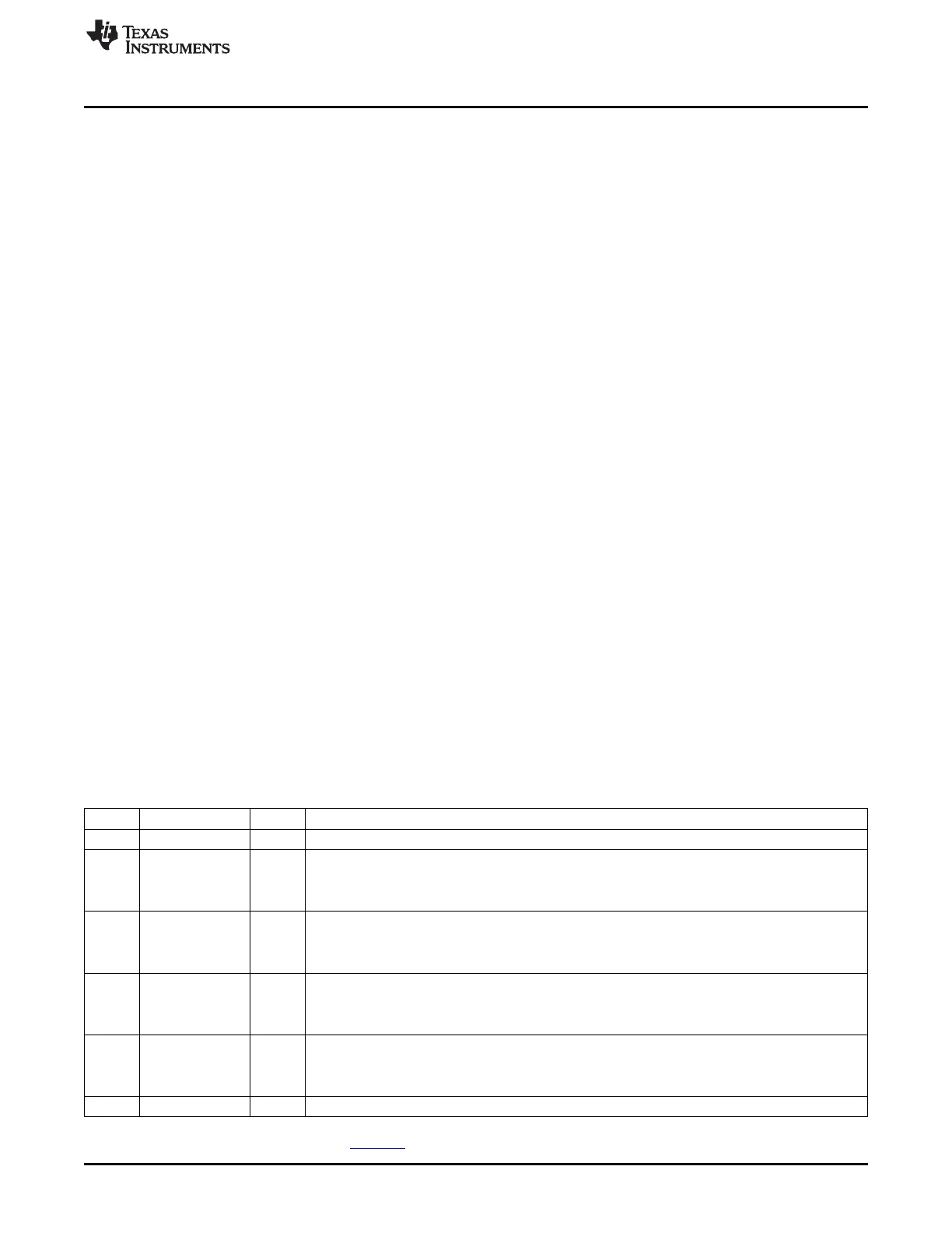
The following table shows the generic Pad Control Register Description.
Table 9-1. Pad Control Register Field Descriptions
Bit Field Value Description
31-7 Reserved Reserved. Read returns 0.
6 SLEWCTRL Select between faster or slower slew rate.
0 Fast
1 Slow
(1)
5 RXACTIVE Input enable value for the Pad. Set to 0 for output only. Set to 1 for input or output.
0 Receiver disabled
1 Receiver enabled
4 PULLTYPESEL Pad pullup/pulldown type selection
0 Pulldown selected
1 Pullup selected
3 PULLUDEN Pad Pullup/pulldown enable
0 Pullup/pulldown enabled.
1 Pullup/pulldown disabled.
2-0 MUXMODE Pad functional signal mux select
(1)
Some peripherals do not support slow slew rate. To determine which interfaces support each slew rate, see AM335x ARM Cortex-A8
Microprocessors (MPUs) (literature number SPRS717).
747
SPRUH73H–October 2011–Revised April 2013 Control Module
Submit Documentation Feedback
Copyright © 2011–2013, Texas Instruments Incorporated

 Loading...


