www.ti.com
DMTimer 1ms
The dedicated output pin (PORTIMERPWM) can be programmed through TCLR (TRG and PT bits) to
generate one positive pulse (TIMER clock duration) or to invert the current value (toggle mode) when an
overflow and a match occur.
20.2.3.4 Prescaler Functionality
A prescaler counter can be used to divide the timer counter input clock frequency. The prescaler is
enabled when TCLR bit 5 is set (PRE). The 2n division ratio value (PTV) can be configured in the TCLR
register.
The prescaler counter is reset when the timer counter is stopped or reloaded on the fly.
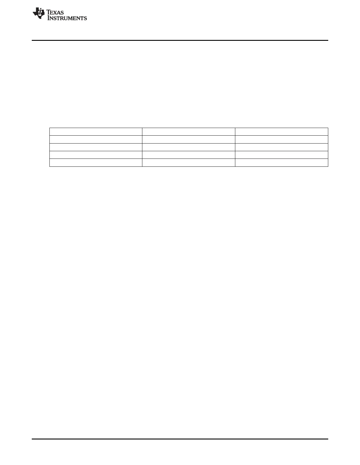
Table 20-31. Prescaler/Timer Reload Values Versus Contexts
Contexts Prescaler Counter Timer Counter
Overflow (when Auto-reload on) reset TLDR
TCRR Write reset TCRR
TTGR Write reset TLDR
Stop reset Frozen
20.2.3.5 Pulse-Width Modulation
The timer can be configured to provide a programmable pulse-width modulation (PORTIMERPWM)
output. The PORTIMERPWM output pin can be configured to toggle on specified event. TCLR (TRG bits)
determines on which register value the PORTIMERPWM pin toggles. Either overflow or match can be
used to toggle the PORTIMERPWM pin, when a compare condition occurs.
In case of overflow and match mode, the match event will be ignored from the moment the mode was set-
up until the first overflow event occurs
The TCLR (SCPWM bit) can be programmed to set or clear the PORTIMERPWM output signal while the
counter is stopped or the triggering is off only. This allows fixing a deterministic state of the output pin
when modulation is stopped. The modulation is synchronously stopped when TRG bit is cleared and
overflow occurred.
In the following timing diagram, the internal overflow pulse is set each time (0xFFFF FFFFF – TLDR +1)
value is reached, and the internal match pulse is set when the counter reaches TMAR register value.
According to TCLR (TRG and PT bits) programming value, the timer provides pulse or PWM on the output
pin (PORTIMERPWM).
The TLDR and TMAR registers must keep values smaller than the overflow value (0xFFFFFFFF) with at
least 2 units. In case the PWM trigger events are both overflow and match, the difference between the
values kept in TMAR register and the value in TLDR must be at least 2 units. When match event is used
the compare mode TCLR (CE) must be set.
On the following wave TCLR (SCPWM bit) is set to ‘0’.
3593
SPRUH73H–October 2011–Revised April 2013 Timers
Submit Documentation Feedback
Copyright © 2011–2013, Texas Instruments Incorporated

 Loading...


